
Introductory Circuit Analysis (13th Edition)
13th Edition
ISBN: 9780133923605
Author: Robert L. Boylestad
Publisher: PEARSON
expand_more
expand_more
format_list_bulleted
Videos
Textbook Question
Chapter 10, Problem 42P
For the circuit in Fig. 10.110:
a. Find the mathematical expressions for the transient behavior of the voltage UC and the current
b. Sketch the waveforms of UC and
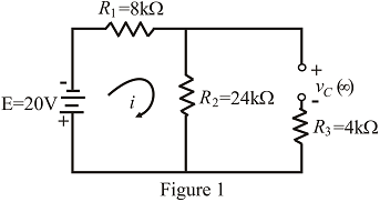
Fig. 10.110
Expert Solution & Answer
Want to see the full answer?
Check out a sample textbook solution
Students have asked these similar questions
Q: - Consider the circuit in Figure
a) What type of circuit is this?
b) Find and Sketch the voltage
waveform across RL, assume
the diodes are practical.
4:1
D,
120 V rms
c) If
sin wave with
100µf
connected in parallel with the
resistor, calculate the ripple
сарacitor
is
60 HZ
1.0 kN
D2
factor
lllee
lelll
AN Sesli oku
1-In the circuit designed to measure the effective value of the sinusoidal voltage at the input, diodes
are considered ideal. M deflection is a measuring element with rotating coil. Rm32k İm-(10)^-4 A.
A-
Draw the waveform of the current flowing through M on a scale. Determine the resistance value of
R1 so that the nominal voltage value of V-m is 100V.
B-What should the tolerances of the resistors be so that the Vm class is at most 1.5? (resistors have
the same tolerances)
ult)
R2
本
R3
20k
18k
R4
k: k2
10k
A clipper circuit based on diodes are simple way to modify waveform
in mechatronics. Assume that the two diodes shown in the circuit
below are ideal diodes. If the input voltage in the circuit is a 1 kHz
sinusoid with peak amplitude of 8V, sketch the Va.. (t)
10 kO
8V
10 kO
Vin
Vin(t)
D2
Vout(t)
RL
Ims
D1
6V
-8V
4V
Page | 1
Chapter 10 Solutions
Introductory Circuit Analysis (13th Edition)
Ch. 10 - a. Find the electric field strength at a point 1 m...Ch. 10 - The electric field strength is 72 newtons/coulomb...Ch. 10 - Find the capacitance of a parallel plate capacitor...Ch. 10 - How much charge is deposited on the plates of a...Ch. 10 - a. Find the electric field strength between the...Ch. 10 - A 6.8 pF parallel plate capacitor has 160 C of...Ch. 10 - Find the capacitance of a parallel plate capacitor...Ch. 10 - Repeat Problem 7 if the dielectric is...Ch. 10 - Find the distance in mils between the plates of a...Ch. 10 - The capacitance of a capacitor with a dielectric...
Ch. 10 - The plates of a parallel plate capacitor with a...Ch. 10 - A parallel plate air capacitor has a capacitance...Ch. 10 - Find the maximum voltage that can be applied...Ch. 10 - Find the distance in micrometers between the...Ch. 10 - A 22 pF capacitor has -200 ppm/C at room...Ch. 10 - What is the capacitance of a small teardrop...Ch. 10 - A large, flat, mica capacitor is labeled 471F....Ch. 10 - A small, flat, disc ceramic capacitor is labeled...Ch. 10 - For the circuit in Fig. 10.94, composed of...Ch. 10 - Repeat Problem 19 for R=100k, and compare the...Ch. 10 - For the circuit in Fig. 10.95, composed of...Ch. 10 - For the circuit in Fig. 10.96, composed of...Ch. 10 - Prob. 23PCh. 10 - The voltage across a 10 F capacitor in a series...Ch. 10 - For the R-C circuit in Fig. 10.97. composed of...Ch. 10 - For the network in Fig. 10.98. composed of...Ch. 10 - For the network in Fig.10.99.composed of standard...Ch. 10 - The 1000 F capacitor in Fig.10.100 is charged to...Ch. 10 - The capacitor in Fig. 10.101 is initially charged...Ch. 10 - Repeat Problem 29 if the initial charge is -40V.Ch. 10 - Repeat Problem 29 if the initial charge is +40V.Ch. 10 - The capacitor in Fig. 10.102 is initially charged...Ch. 10 - The capacitor in Fig. 10.103 is initially charged...Ch. 10 - The capacitor in Fig. 10.104 is initially charged...Ch. 10 - The capacitors of Fig. 10.105 are initially...Ch. 10 - Repeat Problem 35 if a 10 k resistor is placed in...Ch. 10 - Given the expression vc=140mV(1-e-t/2ms) a....Ch. 10 - For the automobile circuit of Fig. 10.106. VL must...Ch. 10 - Design the network in Fig.10.107 such that the...Ch. 10 - For the circuit in Fig. 10.108: a. Find the time...Ch. 10 - For the system in Fig. 10.109. using a DMM with a...Ch. 10 - For the circuit in Fig. 10.110: a. Find the...Ch. 10 - The capacitor in Fig. 10.111 is initially charged...Ch. 10 - The capacitors in Fig. 10.112 are initially...Ch. 10 - For the circuit in Fig. 10.113: a. Find the...Ch. 10 - The capacitor in Fig. 10.114 is initially charged...Ch. 10 - For the system in Fig. 10.115, using a DMM with a...Ch. 10 - Find the waveform for the average current if the...Ch. 10 - Find the waveform for the average current if the...Ch. 10 - Given the waveform in Fig.10.118 for the current...Ch. 10 - Find the total capacitance CT for the network in...Ch. 10 - Find the total capacitance CT for the network in...Ch. 10 - Find the steady-state voltage across and the...Ch. 10 - Find the steady-state voltage across and the...Ch. 10 - For the configuration in Fig. 10.123, determine...Ch. 10 - For the configuration in Fig.10.124, determine the...Ch. 10 - Find the energy stored by a 120 pF capacitor with...Ch. 10 - If the energy stored by a 6 F capacitor is 1200 J,...Ch. 10 - For the network in Fig. 10.125, determine the...Ch. 10 - An electronic flashgun has a 1000 F capacitor that...Ch. 10 - Using PSpice or Multisim, verify the results in...Ch. 10 - Using the initial condition operator, verify the...Ch. 10 - Using PSpice or Multisim, verify the results for...Ch. 10 - Using PSpice or Multisim, verify the results in...
Knowledge Booster


Learn more about
Need a deep-dive on the concept behind this application? Look no further. Learn more about this topic, electrical-engineering and related others by exploring similar questions and additional content below.Similar questions
- The current through the diode in the circuit given in the Figure below when Vy = 0.7 V is? ww 8092 12V Select one a. 24.26 mA b. 13.09 mA c. 58.23 mA d. 40.13 mA 40-52 ww 3092 IDarrow_forward7) sine wave. Sketch the waveform (1 period is enough) for the resulting Vout- What are its positive and negative peak values? (AVforward,ideal = 0) For each of the ideal-diode circuits below, the input Vin is a 1kHz 5-V peak a) b) Vin Vaut Vin Vaut 1kN 1kN c) c) Vin Vout Vin Veut 1kN 1kN e) f) Vin 1kN Vaut Vin 1kN Vout 太太arrow_forward10. The figure below shows a circuit for charging a 12-V battery. If V, is a sinusoid with 24-V peak amplitude, the fraction of each cycle during which the diode conducts is 100 n 12 V a) One quarter of a cycle b) One-third of a cycle c) One half of the cycle d) Three quarters of a cyclearrow_forward
- A diode whose internal resistance is 17 ohm is to supply power to a 2,008 ohm load from a 110V RMS source of supply. Calculate the dc load voltage. Round off your answers to three decimal places.arrow_forwardHalf-wave 50Hz sinusoidal uncontrolled rectifier circuit with a peak voltage value of 100V and a source inductance of 8mH is feeding a highly inductive load of 8A. The average value of the output voltage and power delivered are, respectively and what is the communication angle (u) Power Electronicsarrow_forwardA- If V, is a sinusoidal voltage with Vm = 40 V, and V= 15 V. Plot the waveform of the output voltage in each of the following clippers circuits assuming ideal diodes. B- Repeat part (A) if the diodes are silicon diodes. R R R (a) (b) (c) (d)arrow_forward
- In a rectifier circuit , DC output voltage and RMS output voltage is 0.3 V & 0.55 V respectively. The form factor of this circuit is a. 3.67 b. 0.55 c. 1.35 d. 1.83arrow_forwardExe 1. A half-wave rectifier has a source of 120 V rms at 60 Hz and an R-L load with R=10 Ω and L= 10 mH.Determine, an expression for the load current, the average current, the power absorbed by the resistor, and the power factor. Hint: Beta=3.5 Radarrow_forwardA clipper circuit based on diodes are simple way to modify waveform in mechatronics. Assume that the two diodes shown in the circuit below are ideal diodes. If the input voltage in the circuit is a 1 kHz sinusoid with peak amplitude of 8V, sketch the Vaue (t). 10 k. 8V 10 kN. D2 RL Vourlt) Vin= Vin(t) Ims D1 6V -8V 4V Page | 1arrow_forward
- The circuit below with an ideal diode is used to charge a 12 V battery. vin is a sinusoid with 24 V peak amplitude: vin = 24 sin(⍵t) a) For how long does the diode conduct within each cycle: 1/2 of the cycle time, 1/3 of the cycle time, ¼ of the cycle time, or 1/5 of the cycle time? b) Find the peak value of the diode current and the maximum reverse-bias voltage that appears across the diode.arrow_forward1-In the circuit designed to measure the effective value of the sinusoidal voltage at the input, diodes are considered ideal. M deflection is a measuring element with rotating coil. Rm=2k İm=(10)^-4 A. A- Draw the waveform of the current flowing through M on a scale. Determine the resistance value of R1 so that the nominal voltage value of V-m is 100V. B-What should the tolerances of the resistors be so that the Vm class is at most 1.5? (resistors have the same tolerances). R1 u(t) R2 1R3 18k 20k R4 k: k2 10karrow_forward8. Liquids with solid impurities a) Have higher dielectrie strength b) Of large size have higher dielectric strength c) Have lower dielectric strength as compared to pure liquids d) None of the above 9. Peak to peak ripple is defined as a) the difference between average de voltage and peak value b) the difference between maximum and minimum de voltage c) the difference between maximum ac and average dc voltages d) the difference between ac (rms) and average de voltages 10. In a Cockroft-Walton circuit, input voltage 100 kV load current 25 mA, supply frequency 100 Hz, each capacitor 10 nF. The optimum no. of stages for maximum output voltage is a) 1 b) 2 c) 10 d) 35arrow_forward
arrow_back_ios
SEE MORE QUESTIONS
arrow_forward_ios
Recommended textbooks for you
 Introductory Circuit Analysis (13th Edition)Electrical EngineeringISBN:9780133923605Author:Robert L. BoylestadPublisher:PEARSON
 Delmar's Standard Textbook Of ElectricityElectrical EngineeringISBN:9781337900348Author:Stephen L. HermanPublisher:Cengage Learning
 Programmable Logic ControllersElectrical EngineeringISBN:9780073373843Author:Frank D. PetruzellaPublisher:McGraw-Hill Education
 Fundamentals of Electric CircuitsElectrical EngineeringISBN:9780078028229Author:Charles K Alexander, Matthew SadikuPublisher:McGraw-Hill Education
 Electric Circuits. (11th Edition)Electrical EngineeringISBN:9780134746968Author:James W. Nilsson, Susan RiedelPublisher:PEARSON
 Engineering ElectromagneticsElectrical EngineeringISBN:9780078028151Author:Hayt, William H. (william Hart), Jr, BUCK, John A.Publisher:Mcgraw-hill Education,
Introductory Circuit Analysis (13th Edition)
Electrical Engineering
ISBN:9780133923605
Author:Robert L. Boylestad
Publisher:PEARSON
Delmar's Standard Textbook Of Electricity
Electrical Engineering
ISBN:9781337900348
Author:Stephen L. Herman
Publisher:Cengage Learning
Programmable Logic Controllers
Electrical Engineering
ISBN:9780073373843
Author:Frank D. Petruzella
Publisher:McGraw-Hill Education
Fundamentals of Electric Circuits
Electrical Engineering
ISBN:9780078028229
Author:Charles K Alexander, Matthew Sadiku
Publisher:McGraw-Hill Education
Electric Circuits. (11th Edition)
Electrical Engineering
ISBN:9780134746968
Author:James W. Nilsson, Susan Riedel
Publisher:PEARSON
Engineering Electromagnetics
Electrical Engineering
ISBN:9780078028151
Author:Hayt, William H. (william Hart), Jr, BUCK, John A.
Publisher:Mcgraw-hill Education,
Random Variables and Probability Distributions; Author: Dr Nic's Maths and Stats;https://www.youtube.com/watch?v=lHCpYeFvTs0;License: Standard Youtube License