
Introductory Circuit Analysis (13th Edition)
13th Edition
ISBN: 9780133923605
Author: Robert L. Boylestad
Publisher: PEARSON
expand_more
expand_more
format_list_bulleted
Concept explainers
Videos
Textbook Question
Chapter 10, Problem 50P
Given the waveform in Fig.10.118 for the current of a 20
capacitor, sketch the waveform of the voltage UC across the capacitor if
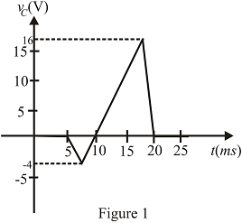
Fig.10.118
Expert Solution & Answer
Want to see the full answer?
Check out a sample textbook solution
Students have asked these similar questions
A capacitor of 4.56 uF capacitance is connected to a d.c. source through a resis tance of 1 megaohm. Calculate the time taken by the capacitor to receive 75% of its final charge. How long will it take the capacitor to be fully charged?
).paf
Find the expression for the voltage and current of both the capacitor and the inductor as a function of time for each of the
following circuits. Sketch the voltage and current as a function of time.
Circuit 1
42
ww
0.02 F=
10 V
30
0.5 H
Circuit 2
t=0
ww
102
3 A
50
1 H
10 mF
ww
The capacitance of a capacitor is directly proportional to:
Ca the frequency of the applied voltage.
b) the plate thickness.
0
C) the dielectric thickness.
d) the plate area.
Chapter 10 Solutions
Introductory Circuit Analysis (13th Edition)
Ch. 10 - a. Find the electric field strength at a point 1 m...Ch. 10 - The electric field strength is 72 newtons/coulomb...Ch. 10 - Find the capacitance of a parallel plate capacitor...Ch. 10 - How much charge is deposited on the plates of a...Ch. 10 - a. Find the electric field strength between the...Ch. 10 - A 6.8 pF parallel plate capacitor has 160 C of...Ch. 10 - Find the capacitance of a parallel plate capacitor...Ch. 10 - Repeat Problem 7 if the dielectric is...Ch. 10 - Find the distance in mils between the plates of a...Ch. 10 - The capacitance of a capacitor with a dielectric...
Ch. 10 - The plates of a parallel plate capacitor with a...Ch. 10 - A parallel plate air capacitor has a capacitance...Ch. 10 - Find the maximum voltage that can be applied...Ch. 10 - Find the distance in micrometers between the...Ch. 10 - A 22 pF capacitor has -200 ppm/C at room...Ch. 10 - What is the capacitance of a small teardrop...Ch. 10 - A large, flat, mica capacitor is labeled 471F....Ch. 10 - A small, flat, disc ceramic capacitor is labeled...Ch. 10 - For the circuit in Fig. 10.94, composed of...Ch. 10 - Repeat Problem 19 for R=100k, and compare the...Ch. 10 - For the circuit in Fig. 10.95, composed of...Ch. 10 - For the circuit in Fig. 10.96, composed of...Ch. 10 - Prob. 23PCh. 10 - The voltage across a 10 F capacitor in a series...Ch. 10 - For the R-C circuit in Fig. 10.97. composed of...Ch. 10 - For the network in Fig. 10.98. composed of...Ch. 10 - For the network in Fig.10.99.composed of standard...Ch. 10 - The 1000 F capacitor in Fig.10.100 is charged to...Ch. 10 - The capacitor in Fig. 10.101 is initially charged...Ch. 10 - Repeat Problem 29 if the initial charge is -40V.Ch. 10 - Repeat Problem 29 if the initial charge is +40V.Ch. 10 - The capacitor in Fig. 10.102 is initially charged...Ch. 10 - The capacitor in Fig. 10.103 is initially charged...Ch. 10 - The capacitor in Fig. 10.104 is initially charged...Ch. 10 - The capacitors of Fig. 10.105 are initially...Ch. 10 - Repeat Problem 35 if a 10 k resistor is placed in...Ch. 10 - Given the expression vc=140mV(1-e-t/2ms) a....Ch. 10 - For the automobile circuit of Fig. 10.106. VL must...Ch. 10 - Design the network in Fig.10.107 such that the...Ch. 10 - For the circuit in Fig. 10.108: a. Find the time...Ch. 10 - For the system in Fig. 10.109. using a DMM with a...Ch. 10 - For the circuit in Fig. 10.110: a. Find the...Ch. 10 - The capacitor in Fig. 10.111 is initially charged...Ch. 10 - The capacitors in Fig. 10.112 are initially...Ch. 10 - For the circuit in Fig. 10.113: a. Find the...Ch. 10 - The capacitor in Fig. 10.114 is initially charged...Ch. 10 - For the system in Fig. 10.115, using a DMM with a...Ch. 10 - Find the waveform for the average current if the...Ch. 10 - Find the waveform for the average current if the...Ch. 10 - Given the waveform in Fig.10.118 for the current...Ch. 10 - Find the total capacitance CT for the network in...Ch. 10 - Find the total capacitance CT for the network in...Ch. 10 - Find the steady-state voltage across and the...Ch. 10 - Find the steady-state voltage across and the...Ch. 10 - For the configuration in Fig. 10.123, determine...Ch. 10 - For the configuration in Fig.10.124, determine the...Ch. 10 - Find the energy stored by a 120 pF capacitor with...Ch. 10 - If the energy stored by a 6 F capacitor is 1200 J,...Ch. 10 - For the network in Fig. 10.125, determine the...Ch. 10 - An electronic flashgun has a 1000 F capacitor that...Ch. 10 - Using PSpice or Multisim, verify the results in...Ch. 10 - Using the initial condition operator, verify the...Ch. 10 - Using PSpice or Multisim, verify the results for...Ch. 10 - Using PSpice or Multisim, verify the results in...
Knowledge Booster


Learn more about
Need a deep-dive on the concept behind this application? Look no further. Learn more about this topic, electrical-engineering and related others by exploring similar questions and additional content below.Similar questions
- Three capacitors having capacitance values of 20F,40F, and 50F are connected in parallel to a 60 - Hz power line. An ammeter indicates a circuit current of 8.6 amperes. How much current is flowing through the 40F capacitor?arrow_forwardA postage stamp mica capacitor has the following color marks starting at the upper left dot: yellow, violet, brown, green, no color, and blue. What are the capacitance value, tolerance, and voltage rating of this capacitor?arrow_forwardInductive Circuits Fill in all the missing values. Refer to the following formulas: XL=2fLL=XL2ff=XL2L Inductance (H) Frequency (Hz) Inductive Reactance ( ) 1.2 60 0.085 213.628 1000 4712.389 0.65 600 3.6 678.584 25 411.459 0.5 60 0.85 6408.849 20 201.062 0.45 400 4.8 2412.743 1000 40.841arrow_forward
- Assume that the current flow through the resistor, IR, is 15 A; the current flow through the inductor, IL is 36 A; and the circuit has an apparent power of 10,803 VA. The frequency of the AC voltage is 60 Hz. ET ER EL IT IR15A IL36A Z R XL VA10,803 P VARSL PF Larrow_forwardWhat is the unit of measurement for the strength of a capacitor? microamp microtorque microfarad microwattarrow_forwardThe circuit is connected to a 60-Hz line. The apparent power in the circuit is 29.985 VA, and the power factor is 62.5%. The resistor has a voltage drop of 14.993 V, the inductor has an inductive reactance of 60 , and the capacitor has a capacitive reactance of 45 . ETITZVA29.985PF62.5%ER14.993VIRRPELILXL60VARsLLECICXC45VARsCCarrow_forward
- Assume that the voltage drop across the resistor, ER, is 78 V, that the voltage drop across the inductor, EL, is 104 V, and the circuit has a total impedance, Z, of 20 . The frequency of the AC voltage is 60 Hz. ETITZ20VAPFER78VIRRPEL104VILXLVARsLLarrow_forwardAssume that the voltage drop across the resistor, ER, is 78 V; the voltage drop across the capacitor, EC, is 104 V; and the circuit has a total impedance, Z, of 20 . The frequency of the AC voltage is 60 Hz. Find the missing values. ET ER78V EC104V IT IR IC Z20 R XC VA P VARSC PF Carrow_forwardWhat frequency must be applied to a 33-mH inductor to produce an inductive reactance of 99.526 ?arrow_forward
- A postage stamp capacitor has the following color marks starting at the upper-left dot: black, orange, orange, black, silver, and white. What are the capacitance value and tolerance of this capacitor?arrow_forwardCapacitive Circuits Fill in all the missing values. Refer to the formulas that follow. XC=12fCC=12fXCf=12CXc Capacitance XC Frequency 38 F 60 Hz 78.8 400 Hz 250 pF 4.5 k 234 F 10 kHZ 240 50 Hz 10 F 36.8 560 nF 2 MHz 15 k 60 Hz 75 nF 560 470 pF 200 kHz 6.8 k 400 Hz 34 F 450arrow_forwardFill in all the missing values. Refer to the formulas that follow. Resistance Capacitance Time constant Total time 150 k 100 F 350 k 35 s 350 pF 10 s 0.05 F 1.2 M 0.47 F 12F 0.05 s 86 k 1.5 s 120 k 470 pF 250 nF 100 ms 8 F 150 s 100 k 150 ms 33 k 4 F =RCR=CC=R Totaltime=5arrow_forward
arrow_back_ios
SEE MORE QUESTIONS
arrow_forward_ios
Recommended textbooks for you
 Delmar's Standard Textbook Of ElectricityElectrical EngineeringISBN:9781337900348Author:Stephen L. HermanPublisher:Cengage Learning
 Electricity for Refrigeration, Heating, and Air C...Mechanical EngineeringISBN:9781337399128Author:Russell E. SmithPublisher:Cengage Learning
Delmar's Standard Textbook Of Electricity
Electrical Engineering
ISBN:9781337900348
Author:Stephen L. Herman
Publisher:Cengage Learning
Electricity for Refrigeration, Heating, and Air C...
Mechanical Engineering
ISBN:9781337399128
Author:Russell E. Smith
Publisher:Cengage Learning
Demos: Dielectric breakdown; Author: Caltech's Feynman Lecture Hall;https://www.youtube.com/watch?v=2YrHh1ikefI;License: Standard Youtube License