
Introductory Circuit Analysis (13th Edition)
13th Edition
ISBN: 9780133923605
Author: Robert L. Boylestad
Publisher: PEARSON
expand_more
expand_more
format_list_bulleted
Videos
Textbook Question
Chapter 10, Problem 33P
The capacitor in Fig. 10.103 is initially charged to 10 V with the polarity shown. Write the expressions for the voltage Uc and the current ic following the dosing of the switch. Plot the resulting waveforms.
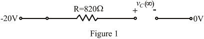
Fig. 10.103
Expert Solution & Answer
Want to see the full answer?
Check out a sample textbook solution
Students have asked these similar questions
1.
1-5 K
30v
a. what is tue T CTime constant) ?
b. How long
will it take for the capacutor TO
rtach s0% op charge?
C. What is tne voltage of capa citor apter
1 seconds?
d. How many tíme constants will it take for the
soltage to reach 23 v?
C. Gweng that the capacitor is fully changed, how
will it take por it to be 20% ?
long
120v
+ BF
what is the. T ?
b. what is the voltage capacitor apter 10 sec?
a.
C. How many time constants will it take for Tue
Vo Itage to reach 80 v.?
d. Given that the capaator is Fully charged, how
time constants will it be to reau
many
GOV!
10 V
sine
90 kHz
1 kQ
C1
1 nF
2. Using a Square function with 90,000 Hz in your function-generator, a 1000-ohm
resistor, and a
1 nano-Farad capacitor, determine the charging time for the capacitor. Show your
calculations and show the charging-discharge curve with an oscilloscope in TINKERCAD.
Describe the behavior of the voltage across the resistor with time as thecapacitor charges. Explain the reason for this behavior.
Chapter 10 Solutions
Introductory Circuit Analysis (13th Edition)
Ch. 10 - a. Find the electric field strength at a point 1 m...Ch. 10 - The electric field strength is 72 newtons/coulomb...Ch. 10 - Find the capacitance of a parallel plate capacitor...Ch. 10 - How much charge is deposited on the plates of a...Ch. 10 - a. Find the electric field strength between the...Ch. 10 - A 6.8 pF parallel plate capacitor has 160 C of...Ch. 10 - Find the capacitance of a parallel plate capacitor...Ch. 10 - Repeat Problem 7 if the dielectric is...Ch. 10 - Find the distance in mils between the plates of a...Ch. 10 - The capacitance of a capacitor with a dielectric...
Ch. 10 - The plates of a parallel plate capacitor with a...Ch. 10 - A parallel plate air capacitor has a capacitance...Ch. 10 - Find the maximum voltage that can be applied...Ch. 10 - Find the distance in micrometers between the...Ch. 10 - A 22 pF capacitor has -200 ppm/C at room...Ch. 10 - What is the capacitance of a small teardrop...Ch. 10 - A large, flat, mica capacitor is labeled 471F....Ch. 10 - A small, flat, disc ceramic capacitor is labeled...Ch. 10 - For the circuit in Fig. 10.94, composed of...Ch. 10 - Repeat Problem 19 for R=100k, and compare the...Ch. 10 - For the circuit in Fig. 10.95, composed of...Ch. 10 - For the circuit in Fig. 10.96, composed of...Ch. 10 - Prob. 23PCh. 10 - The voltage across a 10 F capacitor in a series...Ch. 10 - For the R-C circuit in Fig. 10.97. composed of...Ch. 10 - For the network in Fig. 10.98. composed of...Ch. 10 - For the network in Fig.10.99.composed of standard...Ch. 10 - The 1000 F capacitor in Fig.10.100 is charged to...Ch. 10 - The capacitor in Fig. 10.101 is initially charged...Ch. 10 - Repeat Problem 29 if the initial charge is -40V.Ch. 10 - Repeat Problem 29 if the initial charge is +40V.Ch. 10 - The capacitor in Fig. 10.102 is initially charged...Ch. 10 - The capacitor in Fig. 10.103 is initially charged...Ch. 10 - The capacitor in Fig. 10.104 is initially charged...Ch. 10 - The capacitors of Fig. 10.105 are initially...Ch. 10 - Repeat Problem 35 if a 10 k resistor is placed in...Ch. 10 - Given the expression vc=140mV(1-e-t/2ms) a....Ch. 10 - For the automobile circuit of Fig. 10.106. VL must...Ch. 10 - Design the network in Fig.10.107 such that the...Ch. 10 - For the circuit in Fig. 10.108: a. Find the time...Ch. 10 - For the system in Fig. 10.109. using a DMM with a...Ch. 10 - For the circuit in Fig. 10.110: a. Find the...Ch. 10 - The capacitor in Fig. 10.111 is initially charged...Ch. 10 - The capacitors in Fig. 10.112 are initially...Ch. 10 - For the circuit in Fig. 10.113: a. Find the...Ch. 10 - The capacitor in Fig. 10.114 is initially charged...Ch. 10 - For the system in Fig. 10.115, using a DMM with a...Ch. 10 - Find the waveform for the average current if the...Ch. 10 - Find the waveform for the average current if the...Ch. 10 - Given the waveform in Fig.10.118 for the current...Ch. 10 - Find the total capacitance CT for the network in...Ch. 10 - Find the total capacitance CT for the network in...Ch. 10 - Find the steady-state voltage across and the...Ch. 10 - Find the steady-state voltage across and the...Ch. 10 - For the configuration in Fig. 10.123, determine...Ch. 10 - For the configuration in Fig.10.124, determine the...Ch. 10 - Find the energy stored by a 120 pF capacitor with...Ch. 10 - If the energy stored by a 6 F capacitor is 1200 J,...Ch. 10 - For the network in Fig. 10.125, determine the...Ch. 10 - An electronic flashgun has a 1000 F capacitor that...Ch. 10 - Using PSpice or Multisim, verify the results in...Ch. 10 - Using the initial condition operator, verify the...Ch. 10 - Using PSpice or Multisim, verify the results for...Ch. 10 - Using PSpice or Multisim, verify the results in...
Knowledge Booster


Learn more about
Need a deep-dive on the concept behind this application? Look no further. Learn more about this topic, electrical-engineering and related others by exploring similar questions and additional content below.Similar questions
- a) Examine the charging and discharging phases of the circuits and then answer the following: What is the time constant () of both circuits in each case? Describe the voltage across and the current through the capacitor combination in both charging and discharging phases.arrow_forwardExplain the exponential relationship between the charge on capacitor and time during charging or discharign with the use of natural logarrow_forwardFor a given reaction, AH = -27.7 kJ/mol and AS = -55.5 J/K-mol. The reaction will have at Assume that AH and AS do not vary with temperature. 0.499 2004 2.00 298 499arrow_forward
- 1. Find the voltages across the following components (a and b) after 1 second. The Capacitor is initially charged at 10V while the voltage source is 1V. Resistor R is 103 ohm while capacitor C is 1mF. a. Capacitor C b. Resistor R c. What is the best 1st order DE Method applicable to this problem?arrow_forwardDraw the inductance and resistance voltages on an oscilloscope screen in accordance with their polarity. In the drawing, it should start with voltage changes and values and should be stable. Write the Time/Div and Volt/Div steps made on the oscilloscope during the measurement on the oscilloscope screen drawing. Specify the voltage labels in the drawing. The current through the circuit has the same variation as the resistor voltage measured from the equation V=I/R, but is 1/47 times the value.arrow_forwardA series circuit conducting of a 30-uf capacitor and a 0.155-henry inductor is connected to a 120-volt 60-cycle source. If a variable inductor is substitute instead, what should be its value if an equal current is to lag behind the voltage? Assume all other conditions remain unchangedarrow_forward
- When the switch is in position 2, the circuit will discharge the capacitor. Draw the circuit for the discharge phase. (without any of the charge phase components). and determine the time constant for the discharge phase and the equations for v(t) and i(t) for the discharge phase.arrow_forwardWhich of the following is not a practical type of inductor? O a. SMD Chip Inductor O b. AM Radio Antenna O c. Curie Temperature O d. Toroidal Core Inductorarrow_forwardFull-wave rectified sine wave circuit is used to measure the RMS value of a half square wave with the help of PMMC meter. The meter was actually calibrated for sine wave. The circuit uses a meter movement with a full scale deflection current of 200uA and internal meter resistance of 5kΩ. Assuming Non-ideal diodes having resistance 1kΩ, Analyze the circuit to determine the value of series multiplier resister and the corrected RMS voltage, if meter is to read 225V RMS full-scale.arrow_forward
- Electrical Engineering please solve this thank you The following values are given for a shocdley diode Vi (derel vollaye) • 0.025 V Is (Deverse salunalia cmal): 10X10A -15 Given voltaye eg ^: v(t) = 0.7+ 8 Vr cosut IA RL= 50 0 %3D Find avg. powen diipted in shochly diode € ay.power deliveud to loadarrow_forwardA 20-ohm resistor and a capacitor are connected in series with a battery of 60 volts. At t = 0, there is no charge on the capacitor. Find the capacitance if the current at t = 5 seconds is 3/e^s amperes. Ans. 0.05 Faradsarrow_forwardThe current through the diode in the circuit given in the Figure below when Vy = 0.7 V is? ww 8092 12V Select one a. 24.26 mA b. 13.09 mA c. 58.23 mA d. 40.13 mA 40-52 ww 3092 IDarrow_forward
arrow_back_ios
SEE MORE QUESTIONS
arrow_forward_ios
Recommended textbooks for you
 Introductory Circuit Analysis (13th Edition)Electrical EngineeringISBN:9780133923605Author:Robert L. BoylestadPublisher:PEARSON
 Delmar's Standard Textbook Of ElectricityElectrical EngineeringISBN:9781337900348Author:Stephen L. HermanPublisher:Cengage Learning
 Programmable Logic ControllersElectrical EngineeringISBN:9780073373843Author:Frank D. PetruzellaPublisher:McGraw-Hill Education
 Fundamentals of Electric CircuitsElectrical EngineeringISBN:9780078028229Author:Charles K Alexander, Matthew SadikuPublisher:McGraw-Hill Education
 Electric Circuits. (11th Edition)Electrical EngineeringISBN:9780134746968Author:James W. Nilsson, Susan RiedelPublisher:PEARSON
 Engineering ElectromagneticsElectrical EngineeringISBN:9780078028151Author:Hayt, William H. (william Hart), Jr, BUCK, John A.Publisher:Mcgraw-hill Education,
Introductory Circuit Analysis (13th Edition)
Electrical Engineering
ISBN:9780133923605
Author:Robert L. Boylestad
Publisher:PEARSON
Delmar's Standard Textbook Of Electricity
Electrical Engineering
ISBN:9781337900348
Author:Stephen L. Herman
Publisher:Cengage Learning
Programmable Logic Controllers
Electrical Engineering
ISBN:9780073373843
Author:Frank D. Petruzella
Publisher:McGraw-Hill Education
Fundamentals of Electric Circuits
Electrical Engineering
ISBN:9780078028229
Author:Charles K Alexander, Matthew Sadiku
Publisher:McGraw-Hill Education
Electric Circuits. (11th Edition)
Electrical Engineering
ISBN:9780134746968
Author:James W. Nilsson, Susan Riedel
Publisher:PEARSON
Engineering Electromagnetics
Electrical Engineering
ISBN:9780078028151
Author:Hayt, William H. (william Hart), Jr, BUCK, John A.
Publisher:Mcgraw-hill Education,
Inductors Explained - The basics how inductors work working principle; Author: The Engineering Mindset;https://www.youtube.com/watch?v=KSylo01n5FY;License: Standard Youtube License