
Introductory Circuit Analysis (13th Edition)
13th Edition
ISBN: 9780133923605
Author: Robert L. Boylestad
Publisher: PEARSON
expand_more
expand_more
format_list_bulleted
Videos
Textbook Question
Chapter 10, Problem 29P
The capacitor in Fig. 10.101 is initially charged to 6 V with the polarity shown.
a. Write the expression for the voltage Uc after the switch is closed.
b. Write the expression for the current ic after the switch is closed.
c. Plot the results of parts (a) and (b).
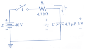
Fig. 10.101
Expert Solution & Answer
Want to see the full answer?
Check out a sample textbook solution
Students have asked these similar questions
Find the distance in mils between the plates of a 2 µF ca-
pacitor if the area of each plate is 0.15 m² and the dielectric
is transformer oil.
11. The capacitance of a capacitor with a dielectric of air is
1200 pF. When a dielectric is inserted between the plates,
the capacitance increases to 6 nF. Of what material is the di-
10.
electric made?
12. The plates of a parallel plate air capacitor are 0.2 mm apart
and have an area of 0.08 m², and 200 V are applied across
the plates.
a. Determine the capacitance.
b. Find the electric field intensity between the plates.
c. Find the charge on each plate if the dielectric is air.
13. A sheet of Bakelite 0.2 mm thick having an area of 0.08 m?
is inserted between the plates of Problem 12.
a. Find the electric field strength between the plates.
b. Determine the charge on each plate.
c. Determine the capacitance.
14. A parallel plate air capacitor has a capacitance of 5 µF. Find
the new capacitance if:
a. The distance between the plates is doubled…
1. Differentiate DC and AC voltage sources in terms of a) value of voltage, b) direction of
current produced, and c) waveform or graph of value versus time.
Based on the graph in no.1a), express the capacitor voltage after one time constant, in
terms of the charging voltage.
Based on the graph in no.1b), express the capacitor voltage after one time constant, in
terms of the initial voltage
SHOW COMPLETE SOLUTION.
A.) Determine the voltage magnitude across the 5 uF capacitor in terms of volts. Use two decimal places.
B.) Determine the angle of the voltage across the 5 uF capacitor in terms of degrees. Use two decimal places.
Chapter 10 Solutions
Introductory Circuit Analysis (13th Edition)
Ch. 10 - a. Find the electric field strength at a point 1 m...Ch. 10 - The electric field strength is 72 newtons/coulomb...Ch. 10 - Find the capacitance of a parallel plate capacitor...Ch. 10 - How much charge is deposited on the plates of a...Ch. 10 - a. Find the electric field strength between the...Ch. 10 - A 6.8 pF parallel plate capacitor has 160 C of...Ch. 10 - Find the capacitance of a parallel plate capacitor...Ch. 10 - Repeat Problem 7 if the dielectric is...Ch. 10 - Find the distance in mils between the plates of a...Ch. 10 - The capacitance of a capacitor with a dielectric...
Ch. 10 - The plates of a parallel plate capacitor with a...Ch. 10 - A parallel plate air capacitor has a capacitance...Ch. 10 - Find the maximum voltage that can be applied...Ch. 10 - Find the distance in micrometers between the...Ch. 10 - A 22 pF capacitor has -200 ppm/C at room...Ch. 10 - What is the capacitance of a small teardrop...Ch. 10 - A large, flat, mica capacitor is labeled 471F....Ch. 10 - A small, flat, disc ceramic capacitor is labeled...Ch. 10 - For the circuit in Fig. 10.94, composed of...Ch. 10 - Repeat Problem 19 for R=100k, and compare the...Ch. 10 - For the circuit in Fig. 10.95, composed of...Ch. 10 - For the circuit in Fig. 10.96, composed of...Ch. 10 - Prob. 23PCh. 10 - The voltage across a 10 F capacitor in a series...Ch. 10 - For the R-C circuit in Fig. 10.97. composed of...Ch. 10 - For the network in Fig. 10.98. composed of...Ch. 10 - For the network in Fig.10.99.composed of standard...Ch. 10 - The 1000 F capacitor in Fig.10.100 is charged to...Ch. 10 - The capacitor in Fig. 10.101 is initially charged...Ch. 10 - Repeat Problem 29 if the initial charge is -40V.Ch. 10 - Repeat Problem 29 if the initial charge is +40V.Ch. 10 - The capacitor in Fig. 10.102 is initially charged...Ch. 10 - The capacitor in Fig. 10.103 is initially charged...Ch. 10 - The capacitor in Fig. 10.104 is initially charged...Ch. 10 - The capacitors of Fig. 10.105 are initially...Ch. 10 - Repeat Problem 35 if a 10 k resistor is placed in...Ch. 10 - Given the expression vc=140mV(1-e-t/2ms) a....Ch. 10 - For the automobile circuit of Fig. 10.106. VL must...Ch. 10 - Design the network in Fig.10.107 such that the...Ch. 10 - For the circuit in Fig. 10.108: a. Find the time...Ch. 10 - For the system in Fig. 10.109. using a DMM with a...Ch. 10 - For the circuit in Fig. 10.110: a. Find the...Ch. 10 - The capacitor in Fig. 10.111 is initially charged...Ch. 10 - The capacitors in Fig. 10.112 are initially...Ch. 10 - For the circuit in Fig. 10.113: a. Find the...Ch. 10 - The capacitor in Fig. 10.114 is initially charged...Ch. 10 - For the system in Fig. 10.115, using a DMM with a...Ch. 10 - Find the waveform for the average current if the...Ch. 10 - Find the waveform for the average current if the...Ch. 10 - Given the waveform in Fig.10.118 for the current...Ch. 10 - Find the total capacitance CT for the network in...Ch. 10 - Find the total capacitance CT for the network in...Ch. 10 - Find the steady-state voltage across and the...Ch. 10 - Find the steady-state voltage across and the...Ch. 10 - For the configuration in Fig. 10.123, determine...Ch. 10 - For the configuration in Fig.10.124, determine the...Ch. 10 - Find the energy stored by a 120 pF capacitor with...Ch. 10 - If the energy stored by a 6 F capacitor is 1200 J,...Ch. 10 - For the network in Fig. 10.125, determine the...Ch. 10 - An electronic flashgun has a 1000 F capacitor that...Ch. 10 - Using PSpice or Multisim, verify the results in...Ch. 10 - Using the initial condition operator, verify the...Ch. 10 - Using PSpice or Multisim, verify the results for...Ch. 10 - Using PSpice or Multisim, verify the results in...
Knowledge Booster


Learn more about
Need a deep-dive on the concept behind this application? Look no further. Learn more about this topic, electrical-engineering and related others by exploring similar questions and additional content below.Similar questions
- A capacitor uses air as a dielectric and has a capacitance of 3 F. A dielectric material is inserted between the plates without changing the spacing, and the capacitance becomes 15 F. What is the dielectric constant of this material?arrow_forwardThree capacitors having capacitance values of 20F,40F, and 50F are connected in parallel to a 60 - Hz power line. An ammeter indicates a circuit current of 8.6 amperes. How much current is flowing through the 40F capacitor?arrow_forwardSolve the following values in figure 1.0. Total Capacitance, Ct. Total Charge, Qt. Individual Charge of C1 Individual Charge of C2 Individual Charge of C3arrow_forward
- 10 V sine 90 kHz 1 kQ C1 1 nF 2. Using a Square function with 90,000 Hz in your function-generator, a 1000-ohm resistor, and a 1 nano-Farad capacitor, determine the charging time for the capacitor. Show your calculations and show the charging-discharge curve with an oscilloscope in TINKERCAD.arrow_forwardWhen the switch is in position 1, the circuit will charge the capacitor. Determine the equations for v(t) and i(t) for the charge phase and determine the voltage and current at time, t = 31 ms, in the charge phase.arrow_forwardAll six capacitors have equal value of 10.0 µF. Determine: a. The equivalent capacitance if measured between points A and B – that is, if the probes of the LCR meter are placed across points A and B, what will the meter show, and b. If a power supply is now attached to the points A and B and set to 20.0 volts, what charge will appear on C1 and what will be the potential difference across C1? C2 C1 В C3 C4 C5 C6arrow_forward
- In the box below, show that the time constant r is the time it takes the voltage across a discharging capacitor to reach the value V0/e.arrow_forwardFor a given reaction, AH = -27.7 kJ/mol and AS = -55.5 J/K-mol. The reaction will have at Assume that AH and AS do not vary with temperature. 0.499 2004 2.00 298 499arrow_forwarda) Examine the charging and discharging phases of the circuits and then answer the following: What is the time constant () of both circuits in each case? Describe the voltage across and the current through the capacitor combination in both charging and discharging phases.arrow_forward
- 1. Find the voltages across the following components (a and b) after 1 second. The Capacitor is initially charged at 10V while the voltage source is 1V. Resistor R is 103 ohm while capacitor C is 1mF. a. Capacitor C b. Resistor R c. What is the best 1st order DE Method applicable to this problem?arrow_forwardWhen the switch is in position 2, the circuit will discharge the capacitor. Draw the circuit for the discharge phase. (without any of the charge phase components). and determine the time constant for the discharge phase and the equations for v(t) and i(t) for the discharge phase.arrow_forward2. A parallel plate capacitor 6 mm apart, the area of each plate is 12 cm². The space between the two plates is filled with a dielectric material with K-10. If the capacitor is given a potential difference of 12 Volts, determine: a. Capacitance of capacitorb. Charge on capacitorarrow_forward
arrow_back_ios
SEE MORE QUESTIONS
arrow_forward_ios
Recommended textbooks for you
 Delmar's Standard Textbook Of ElectricityElectrical EngineeringISBN:9781337900348Author:Stephen L. HermanPublisher:Cengage Learning
Delmar's Standard Textbook Of Electricity
Electrical Engineering
ISBN:9781337900348
Author:Stephen L. Herman
Publisher:Cengage Learning
Inductors Explained - The basics how inductors work working principle; Author: The Engineering Mindset;https://www.youtube.com/watch?v=KSylo01n5FY;License: Standard Youtube License