
Introductory Circuit Analysis (13th Edition)
13th Edition
ISBN: 9780133923605
Author: Robert L. Boylestad
Publisher: PEARSON
expand_more
expand_more
format_list_bulleted
Videos
Textbook Question
Chapter 10, Problem 46P
The capacitor in Fig. 10.114 is initially charged to 8 V with the polarity shown.
a. Write the mathematical expressions for the voltage UC and the current iC when the switch is closed.
b. Sketch the waveforms of UC and iC.
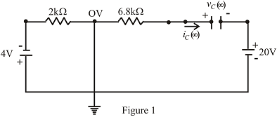
Fig.10.114
Expert Solution & Answer
Want to see the full answer?
Check out a sample textbook solution
Students have asked these similar questions
1.
1-5 K
30v
a. what is tue T CTime constant) ?
b. How long
will it take for the capacutor TO
rtach s0% op charge?
C. What is tne voltage of capa citor apter
1 seconds?
d. How many tíme constants will it take for the
soltage to reach 23 v?
C. Gweng that the capacitor is fully changed, how
will it take por it to be 20% ?
long
120v
+ BF
what is the. T ?
b. what is the voltage capacitor apter 10 sec?
a.
C. How many time constants will it take for Tue
Vo Itage to reach 80 v.?
d. Given that the capaator is Fully charged, how
time constants will it be to reau
many
GOV!
10 V
sine
90 kHz
1 kQ
C1
1 nF
2. Using a Square function with 90,000 Hz in your function-generator, a 1000-ohm
resistor, and a
1 nano-Farad capacitor, determine the charging time for the capacitor. Show your
calculations and show the charging-discharge curve with an oscilloscope in TINKERCAD.
Explain the exponential relationship between the charge on capacitor and time during charging or discharign with the use of natural log
Chapter 10 Solutions
Introductory Circuit Analysis (13th Edition)
Ch. 10 - a. Find the electric field strength at a point 1 m...Ch. 10 - The electric field strength is 72 newtons/coulomb...Ch. 10 - Find the capacitance of a parallel plate capacitor...Ch. 10 - How much charge is deposited on the plates of a...Ch. 10 - a. Find the electric field strength between the...Ch. 10 - A 6.8 pF parallel plate capacitor has 160 C of...Ch. 10 - Find the capacitance of a parallel plate capacitor...Ch. 10 - Repeat Problem 7 if the dielectric is...Ch. 10 - Find the distance in mils between the plates of a...Ch. 10 - The capacitance of a capacitor with a dielectric...
Ch. 10 - The plates of a parallel plate capacitor with a...Ch. 10 - A parallel plate air capacitor has a capacitance...Ch. 10 - Find the maximum voltage that can be applied...Ch. 10 - Find the distance in micrometers between the...Ch. 10 - A 22 pF capacitor has -200 ppm/C at room...Ch. 10 - What is the capacitance of a small teardrop...Ch. 10 - A large, flat, mica capacitor is labeled 471F....Ch. 10 - A small, flat, disc ceramic capacitor is labeled...Ch. 10 - For the circuit in Fig. 10.94, composed of...Ch. 10 - Repeat Problem 19 for R=100k, and compare the...Ch. 10 - For the circuit in Fig. 10.95, composed of...Ch. 10 - For the circuit in Fig. 10.96, composed of...Ch. 10 - Prob. 23PCh. 10 - The voltage across a 10 F capacitor in a series...Ch. 10 - For the R-C circuit in Fig. 10.97. composed of...Ch. 10 - For the network in Fig. 10.98. composed of...Ch. 10 - For the network in Fig.10.99.composed of standard...Ch. 10 - The 1000 F capacitor in Fig.10.100 is charged to...Ch. 10 - The capacitor in Fig. 10.101 is initially charged...Ch. 10 - Repeat Problem 29 if the initial charge is -40V.Ch. 10 - Repeat Problem 29 if the initial charge is +40V.Ch. 10 - The capacitor in Fig. 10.102 is initially charged...Ch. 10 - The capacitor in Fig. 10.103 is initially charged...Ch. 10 - The capacitor in Fig. 10.104 is initially charged...Ch. 10 - The capacitors of Fig. 10.105 are initially...Ch. 10 - Repeat Problem 35 if a 10 k resistor is placed in...Ch. 10 - Given the expression vc=140mV(1-e-t/2ms) a....Ch. 10 - For the automobile circuit of Fig. 10.106. VL must...Ch. 10 - Design the network in Fig.10.107 such that the...Ch. 10 - For the circuit in Fig. 10.108: a. Find the time...Ch. 10 - For the system in Fig. 10.109. using a DMM with a...Ch. 10 - For the circuit in Fig. 10.110: a. Find the...Ch. 10 - The capacitor in Fig. 10.111 is initially charged...Ch. 10 - The capacitors in Fig. 10.112 are initially...Ch. 10 - For the circuit in Fig. 10.113: a. Find the...Ch. 10 - The capacitor in Fig. 10.114 is initially charged...Ch. 10 - For the system in Fig. 10.115, using a DMM with a...Ch. 10 - Find the waveform for the average current if the...Ch. 10 - Find the waveform for the average current if the...Ch. 10 - Given the waveform in Fig.10.118 for the current...Ch. 10 - Find the total capacitance CT for the network in...Ch. 10 - Find the total capacitance CT for the network in...Ch. 10 - Find the steady-state voltage across and the...Ch. 10 - Find the steady-state voltage across and the...Ch. 10 - For the configuration in Fig. 10.123, determine...Ch. 10 - For the configuration in Fig.10.124, determine the...Ch. 10 - Find the energy stored by a 120 pF capacitor with...Ch. 10 - If the energy stored by a 6 F capacitor is 1200 J,...Ch. 10 - For the network in Fig. 10.125, determine the...Ch. 10 - An electronic flashgun has a 1000 F capacitor that...Ch. 10 - Using PSpice or Multisim, verify the results in...Ch. 10 - Using the initial condition operator, verify the...Ch. 10 - Using PSpice or Multisim, verify the results for...Ch. 10 - Using PSpice or Multisim, verify the results in...
Knowledge Booster


Learn more about
Need a deep-dive on the concept behind this application? Look no further. Learn more about this topic, electrical-engineering and related others by exploring similar questions and additional content below.Similar questions
- A capacitor uses air as a dielectric and has a capacitance of 3 F. A dielectric material is inserted between the plates without changing the spacing, and the capacitance becomes 15 F. What is the dielectric constant of this material?arrow_forwardThree capacitors having capacitance values of 20F,40F, and 50F are connected in parallel to a 60 - Hz power line. An ammeter indicates a circuit current of 8.6 amperes. How much current is flowing through the 40F capacitor?arrow_forwardSolve the following values in figure 1.0. Total Capacitance, Ct. Total Charge, Qt. Individual Charge of C1 Individual Charge of C2 Individual Charge of C3arrow_forward
- When the switch is in position 1, the circuit will charge the capacitor. Determine the equations for v(t) and i(t) for the charge phase and determine the voltage and current at time, t = 31 ms, in the charge phase.arrow_forwardIdentify the statement from the following when the inductance can have high value. a. All the given options O b. If the number of turns of the wire is more O c. If the length of the wire is longer O d. If the cross-sectional area is lessarrow_forwardWhat is the value of the induced voltage of the self-inductance when the rate of current is from 200 uA to 20 uA and the total time interval is 5 uS?arrow_forward
- Calculate the voltage across the capacitor in the circuit in the figure and plot the charging curve on the graph.arrow_forwardAC 15. What would the equivalent resistance be of a 159 uF capacitor? 16. What is the RMS voltage of a circuit if the peak voltage is 170 volts? 17. If the RMS voltage is 240 volts AC, what is the peak voltage? 18. What is the formula for finding an inductors equivalent resistance? 19. What is the equivalent resistance of an inductor with 0.17 henrys? 20. What is the symbol of an AC power source? 21. What is the equivalent inductance of a parallel circuit with a 0.01L, 0.02L, and 1.7L inductor? 22. What is the equivalent inductance of a series circuit with a 0.03L, 0.04L, and 1.6L inductor? 23. A transformer with a primary voltage of 480 volts and a turns ratio of 2:1 will have what secondary voltage? 24. A Power Network is comprised of what three components? 25. What is the main difference between a fuse and a circuit breaker?arrow_forward25/ Identify the statement from the following when the inductance can have low value. a. If the number of turns of the wire is less b. If the cross-sectional area is lesser c. If the length of the wire is longer d. All the given optionsarrow_forward
- 1. Differentiate DC and AC voltage sources in terms of a) value of voltage, b) direction of current produced, and c) waveform or graph of value versus time. Based on the graph in no.1a), express the capacitor voltage after one time constant, in terms of the charging voltage. Based on the graph in no.1b), express the capacitor voltage after one time constant, in terms of the initial voltagearrow_forwardDescribe the behavior of the voltage across the resistor with time as thecapacitor charges. Explain the reason for this behavior.arrow_forward11:03 b C Pmark question If the forward voltage drop on a diode is 774 mV, what is the current passing through it? Assume I s =3,4x10⁻¹⁶ A. If the forward voltage drop across a diode is 774 mV, what is the current flowing through it? Is =3.4x10 Get an A. -16 ( a. 2,885 mA b. 4,327 mA c. 3,606 mA D. 2,163 mA O to. 5,048 mA { * . . 51% - Previous page ||| Next page ← Announcements - Teams code: fmf9zv7 <arrow_forward
arrow_back_ios
SEE MORE QUESTIONS
arrow_forward_ios
Recommended textbooks for you
 Delmar's Standard Textbook Of ElectricityElectrical EngineeringISBN:9781337900348Author:Stephen L. HermanPublisher:Cengage Learning
Delmar's Standard Textbook Of Electricity
Electrical Engineering
ISBN:9781337900348
Author:Stephen L. Herman
Publisher:Cengage Learning
Inductors Explained - The basics how inductors work working principle; Author: The Engineering Mindset;https://www.youtube.com/watch?v=KSylo01n5FY;License: Standard Youtube License