
Introductory Circuit Analysis (13th Edition)
13th Edition
ISBN: 9780133923605
Author: Robert L. Boylestad
Publisher: PEARSON
expand_more
expand_more
format_list_bulleted
Concept explainers
Videos
Textbook Question
Chapter 10, Problem 38P
For the automobile circuit of Fig. 10.106. VL must be 8 V before the system is activated, If the switch is closed at
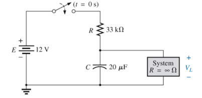
Fig. 10.106
Expert Solution & Answer
Want to see the full answer?
Check out a sample textbook solution
Students have asked these similar questions
in a work environment 50 Hz 220V Find the following hardware in the
power system
1.. .piece 100W incandescent filament lamp
2.power.. .kW efficient %88 power factor 0.85 asynchronous
motor with
3.power 2000W a heater with
power factor of the power system. .Calculate the capacity of
the capacitor that needs to be added to the circuit in order to
determine the places to be written in the blank
Find the following: (Please show complete solution)
- Current after 3.3kohms resistor
- Current after 1Okohms resistor
- Current after 50kohms@50% variable resistor
Given ans.: 720.825 µA, 512.396 µµA, 208.43 µA
AIVIIVI II
720.825µA
S9
R17
3.3k
R18
10k
50%
V9
www
RP2
50k.
RMM12
XMM13
LED
LED1
1.497V
1.411V
A 2.62 ko resistor is connected to an AC voltage source with an rms voltage of 230 V.
(a) What is the maximum potential difference across the resistor (in V)?
V
(b) What is the maximum current through the resistor (in A)?
A
Chapter 10 Solutions
Introductory Circuit Analysis (13th Edition)
Ch. 10 - a. Find the electric field strength at a point 1 m...Ch. 10 - The electric field strength is 72 newtons/coulomb...Ch. 10 - Find the capacitance of a parallel plate capacitor...Ch. 10 - How much charge is deposited on the plates of a...Ch. 10 - a. Find the electric field strength between the...Ch. 10 - A 6.8 pF parallel plate capacitor has 160 C of...Ch. 10 - Find the capacitance of a parallel plate capacitor...Ch. 10 - Repeat Problem 7 if the dielectric is...Ch. 10 - Find the distance in mils between the plates of a...Ch. 10 - The capacitance of a capacitor with a dielectric...
Ch. 10 - The plates of a parallel plate capacitor with a...Ch. 10 - A parallel plate air capacitor has a capacitance...Ch. 10 - Find the maximum voltage that can be applied...Ch. 10 - Find the distance in micrometers between the...Ch. 10 - A 22 pF capacitor has -200 ppm/C at room...Ch. 10 - What is the capacitance of a small teardrop...Ch. 10 - A large, flat, mica capacitor is labeled 471F....Ch. 10 - A small, flat, disc ceramic capacitor is labeled...Ch. 10 - For the circuit in Fig. 10.94, composed of...Ch. 10 - Repeat Problem 19 for R=100k, and compare the...Ch. 10 - For the circuit in Fig. 10.95, composed of...Ch. 10 - For the circuit in Fig. 10.96, composed of...Ch. 10 - Prob. 23PCh. 10 - The voltage across a 10 F capacitor in a series...Ch. 10 - For the R-C circuit in Fig. 10.97. composed of...Ch. 10 - For the network in Fig. 10.98. composed of...Ch. 10 - For the network in Fig.10.99.composed of standard...Ch. 10 - The 1000 F capacitor in Fig.10.100 is charged to...Ch. 10 - The capacitor in Fig. 10.101 is initially charged...Ch. 10 - Repeat Problem 29 if the initial charge is -40V.Ch. 10 - Repeat Problem 29 if the initial charge is +40V.Ch. 10 - The capacitor in Fig. 10.102 is initially charged...Ch. 10 - The capacitor in Fig. 10.103 is initially charged...Ch. 10 - The capacitor in Fig. 10.104 is initially charged...Ch. 10 - The capacitors of Fig. 10.105 are initially...Ch. 10 - Repeat Problem 35 if a 10 k resistor is placed in...Ch. 10 - Given the expression vc=140mV(1-e-t/2ms) a....Ch. 10 - For the automobile circuit of Fig. 10.106. VL must...Ch. 10 - Design the network in Fig.10.107 such that the...Ch. 10 - For the circuit in Fig. 10.108: a. Find the time...Ch. 10 - For the system in Fig. 10.109. using a DMM with a...Ch. 10 - For the circuit in Fig. 10.110: a. Find the...Ch. 10 - The capacitor in Fig. 10.111 is initially charged...Ch. 10 - The capacitors in Fig. 10.112 are initially...Ch. 10 - For the circuit in Fig. 10.113: a. Find the...Ch. 10 - The capacitor in Fig. 10.114 is initially charged...Ch. 10 - For the system in Fig. 10.115, using a DMM with a...Ch. 10 - Find the waveform for the average current if the...Ch. 10 - Find the waveform for the average current if the...Ch. 10 - Given the waveform in Fig.10.118 for the current...Ch. 10 - Find the total capacitance CT for the network in...Ch. 10 - Find the total capacitance CT for the network in...Ch. 10 - Find the steady-state voltage across and the...Ch. 10 - Find the steady-state voltage across and the...Ch. 10 - For the configuration in Fig. 10.123, determine...Ch. 10 - For the configuration in Fig.10.124, determine the...Ch. 10 - Find the energy stored by a 120 pF capacitor with...Ch. 10 - If the energy stored by a 6 F capacitor is 1200 J,...Ch. 10 - For the network in Fig. 10.125, determine the...Ch. 10 - An electronic flashgun has a 1000 F capacitor that...Ch. 10 - Using PSpice or Multisim, verify the results in...Ch. 10 - Using the initial condition operator, verify the...Ch. 10 - Using PSpice or Multisim, verify the results for...Ch. 10 - Using PSpice or Multisim, verify the results in...
Additional Engineering Textbook Solutions
Find more solutions based on key concepts
Electric power systems provide energy in a variety of commercial and industrial settings. Make a list of system...
Principles and Applications of Electrical Engineering
Does the severity of an electric shock increase ordecrease with eh of the following changes? a. A decrease in t...
Electric Motors and Control Systems
What is the color code for a 365- five-band precision resistor with a tolerance of 5 percent?
ELECTRICITY FOR TRADES (LOOSELEAF)
The current source in the circuit shown generates the current pulse
Find (a) v (0); (b) the instant of time gr...
Electric Circuits. (11th Edition)
Identify the type of input and output configuration for each diff-amp in Figure 18-35.
Electronics Fundamentals: Circuits, Devices & Applications
With respect to the circuit in Fig. 5.90, (a) employ Thévenin’s theorem to determine the equivalent network see...
Loose Leaf for Engineering Circuit Analysis Format: Loose-leaf
Knowledge Booster


Learn more about
Need a deep-dive on the concept behind this application? Look no further. Learn more about this topic, electrical-engineering and related others by exploring similar questions and additional content below.Similar questions
- 120 * 8F what is the T ? b. what is the voitage capactor apter 10 sec? c. How many a. time constants will it toake for tue do Itage to reach 8o v.? d. Given that the capacator is Fully Charged, how time constants will it be to reah many GOVarrow_forwardThe energy meter constant is given by (a) revolutions - Wh (b) revolutions – kWh (c) revolutions / Wh (d) revolutions /kWharrow_forwardTOPIC: Fundamentals of Alternating Current Powers Give illustration and a step by step solution. Final answer must be in 4 decimal places. 1. A load takes 55kW at 70% power factor lagging from a 240V, 50Hz supply. If the supply is made 60Hz, with the voltage remaining the same, what will be the kW load at 60Hz? 2. An inductive coil takes a current of 2A and consumes 160W when connected to a 240V supply. A second coil when connected across the same supply takes 3A and 500W. Find the total power when the two coils are connected in series to the supply. 3. A series RC circuit is connected to 230V, 60Hz source. If the power taken by the circuit is 4,800W and the voltage drop across the resistor is 115V, calculate the capacitance of the capacitor. Thank You in advance!arrow_forward
- A battery has a supply rate of 2 amps. How many coulombs did the battery delivered in 24 hrs? Select the correct response: none of the above 1.72 x 10^8 C 1.72 x 10^5 C 2.592 x 10^5 C 2.592 x 10^8 Carrow_forwardElectrical Engineering Given a Darlington Circuit, with the following parameters: +Vcc Ic Rg B V, o- I, VRE B2 VBE, RE Vcc = 23 V B1 = 86 B2 = 114 %3D RB = 6 MegaOhms RE = 346 Ohms Calculate the base current I81 in micro-ampere. Express your answers in 3 decimal placesarrow_forward1 b b 9:1Y ۱۳ ۱ من ۱۳ ۱ For the circuit in figure below, he value of 12 when V2=0 V is 50 6 A sa 0.5 V 20 امجد جاسم کاظم/A/ 9:11p äclull 21.05.31 •.. :arrow_forward
- Q1// For the circuit shown Plot curve between V and I When voltage variable Vin 0.1 0.2 0.3 0.7 0.8 0.9 1 2 3 10 Vf If 1 kOhm Variable DC Voltage .OV اما heel 100 موعد —arrow_forwardTMLINE 50 Hz( NEED NEAT HANDWRITTEN SOLUTION ONLY OTHERWISE DOWNVOTE).arrow_forward1) Consider the circuit shown. Calculate the potential difference across each resistor and the current through each resistor. 50,0 Q 100.0 Q 9.0V 50.0 Q 150.0 Qarrow_forward
- docs.google.com 8 1. What are the values of the resistances bellow according to these colors? a. Orange – blue - green - gold b. Violet – yellow – violet – silver c. Yellow – gray - green - orange - gold d. Blue - brown- red- orange - gold – red 1 Add file 2. How can you connect Avometer to measure current, voltage and resistance? * Your answer 3- how can you examine the capacitor and diode if they work or not ? *arrow_forward11 Design the energy metering unit to measure the energy consumed by 1000 W 230 V fan using Atmel microcontroller programmed using C language on proteus.arrow_forwardListen A JFET that is operating as a voltage-controlled resistance is O all choices in this question are correct answers is operating in the ohmic region has minimum resistance at VGS = 0 typically biased near the origin not as linear as electromechanical potentiometerarrow_forward
arrow_back_ios
SEE MORE QUESTIONS
arrow_forward_ios
Recommended textbooks for you
 Introductory Circuit Analysis (13th Edition)Electrical EngineeringISBN:9780133923605Author:Robert L. BoylestadPublisher:PEARSON
 Delmar's Standard Textbook Of ElectricityElectrical EngineeringISBN:9781337900348Author:Stephen L. HermanPublisher:Cengage Learning
 Programmable Logic ControllersElectrical EngineeringISBN:9780073373843Author:Frank D. PetruzellaPublisher:McGraw-Hill Education
 Fundamentals of Electric CircuitsElectrical EngineeringISBN:9780078028229Author:Charles K Alexander, Matthew SadikuPublisher:McGraw-Hill Education
 Electric Circuits. (11th Edition)Electrical EngineeringISBN:9780134746968Author:James W. Nilsson, Susan RiedelPublisher:PEARSON
 Engineering ElectromagneticsElectrical EngineeringISBN:9780078028151Author:Hayt, William H. (william Hart), Jr, BUCK, John A.Publisher:Mcgraw-hill Education,
Introductory Circuit Analysis (13th Edition)
Electrical Engineering
ISBN:9780133923605
Author:Robert L. Boylestad
Publisher:PEARSON
Delmar's Standard Textbook Of Electricity
Electrical Engineering
ISBN:9781337900348
Author:Stephen L. Herman
Publisher:Cengage Learning
Programmable Logic Controllers
Electrical Engineering
ISBN:9780073373843
Author:Frank D. Petruzella
Publisher:McGraw-Hill Education
Fundamentals of Electric Circuits
Electrical Engineering
ISBN:9780078028229
Author:Charles K Alexander, Matthew Sadiku
Publisher:McGraw-Hill Education
Electric Circuits. (11th Edition)
Electrical Engineering
ISBN:9780134746968
Author:James W. Nilsson, Susan Riedel
Publisher:PEARSON
Engineering Electromagnetics
Electrical Engineering
ISBN:9780078028151
Author:Hayt, William H. (william Hart), Jr, BUCK, John A.
Publisher:Mcgraw-hill Education,
What is an electric furnace and how does it work?; Author: Fire & Ice Heating and Air Conditioning Inc;https://www.youtube.com/watch?v=wjAWecPGi0M;License: Standard Youtube License