
Introductory Circuit Analysis (13th Edition)
13th Edition
ISBN: 9780133923605
Author: Robert L. Boylestad
Publisher: PEARSON
expand_more
expand_more
format_list_bulleted
Concept explainers
Videos
Textbook Question
Chapter 10, Problem 54P
Find the steady-state voltage across and the charge on each capacitor for the circuit in Fig.10.122.
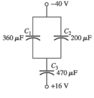
Fig.10.122
Expert Solution & Answer
Want to see the full answer?
Check out a sample textbook solution
Students have asked these similar questions
Assuming the dielectric of each capacitor is air and the network is connected to Vab = 30V supply, calculate the following:a. The equivalent capacitance between a and b.b. The charge on each capacitor.c. The potential difference on each capacitord. Energy stored on each capacitor
Under dc conditions, find the energy stored in the inductor in Joules. Give only the numeric value.
60
9V
10
www
www.
302
2 H
ell
For the network of fig
a- Find the total capacitance.
6.Determine the charge on each plate.
C. Finel the total charge.
d. Determine the
Energig stored
by each capacitor.
40MF
50 HF
20V C
30 UF
C2
C3
Q3
1,
Chapter 10 Solutions
Introductory Circuit Analysis (13th Edition)
Ch. 10 - a. Find the electric field strength at a point 1 m...Ch. 10 - The electric field strength is 72 newtons/coulomb...Ch. 10 - Find the capacitance of a parallel plate capacitor...Ch. 10 - How much charge is deposited on the plates of a...Ch. 10 - a. Find the electric field strength between the...Ch. 10 - A 6.8 pF parallel plate capacitor has 160 C of...Ch. 10 - Find the capacitance of a parallel plate capacitor...Ch. 10 - Repeat Problem 7 if the dielectric is...Ch. 10 - Find the distance in mils between the plates of a...Ch. 10 - The capacitance of a capacitor with a dielectric...
Ch. 10 - The plates of a parallel plate capacitor with a...Ch. 10 - A parallel plate air capacitor has a capacitance...Ch. 10 - Find the maximum voltage that can be applied...Ch. 10 - Find the distance in micrometers between the...Ch. 10 - A 22 pF capacitor has -200 ppm/C at room...Ch. 10 - What is the capacitance of a small teardrop...Ch. 10 - A large, flat, mica capacitor is labeled 471F....Ch. 10 - A small, flat, disc ceramic capacitor is labeled...Ch. 10 - For the circuit in Fig. 10.94, composed of...Ch. 10 - Repeat Problem 19 for R=100k, and compare the...Ch. 10 - For the circuit in Fig. 10.95, composed of...Ch. 10 - For the circuit in Fig. 10.96, composed of...Ch. 10 - Prob. 23PCh. 10 - The voltage across a 10 F capacitor in a series...Ch. 10 - For the R-C circuit in Fig. 10.97. composed of...Ch. 10 - For the network in Fig. 10.98. composed of...Ch. 10 - For the network in Fig.10.99.composed of standard...Ch. 10 - The 1000 F capacitor in Fig.10.100 is charged to...Ch. 10 - The capacitor in Fig. 10.101 is initially charged...Ch. 10 - Repeat Problem 29 if the initial charge is -40V.Ch. 10 - Repeat Problem 29 if the initial charge is +40V.Ch. 10 - The capacitor in Fig. 10.102 is initially charged...Ch. 10 - The capacitor in Fig. 10.103 is initially charged...Ch. 10 - The capacitor in Fig. 10.104 is initially charged...Ch. 10 - The capacitors of Fig. 10.105 are initially...Ch. 10 - Repeat Problem 35 if a 10 k resistor is placed in...Ch. 10 - Given the expression vc=140mV(1-e-t/2ms) a....Ch. 10 - For the automobile circuit of Fig. 10.106. VL must...Ch. 10 - Design the network in Fig.10.107 such that the...Ch. 10 - For the circuit in Fig. 10.108: a. Find the time...Ch. 10 - For the system in Fig. 10.109. using a DMM with a...Ch. 10 - For the circuit in Fig. 10.110: a. Find the...Ch. 10 - The capacitor in Fig. 10.111 is initially charged...Ch. 10 - The capacitors in Fig. 10.112 are initially...Ch. 10 - For the circuit in Fig. 10.113: a. Find the...Ch. 10 - The capacitor in Fig. 10.114 is initially charged...Ch. 10 - For the system in Fig. 10.115, using a DMM with a...Ch. 10 - Find the waveform for the average current if the...Ch. 10 - Find the waveform for the average current if the...Ch. 10 - Given the waveform in Fig.10.118 for the current...Ch. 10 - Find the total capacitance CT for the network in...Ch. 10 - Find the total capacitance CT for the network in...Ch. 10 - Find the steady-state voltage across and the...Ch. 10 - Find the steady-state voltage across and the...Ch. 10 - For the configuration in Fig. 10.123, determine...Ch. 10 - For the configuration in Fig.10.124, determine the...Ch. 10 - Find the energy stored by a 120 pF capacitor with...Ch. 10 - If the energy stored by a 6 F capacitor is 1200 J,...Ch. 10 - For the network in Fig. 10.125, determine the...Ch. 10 - An electronic flashgun has a 1000 F capacitor that...Ch. 10 - Using PSpice or Multisim, verify the results in...Ch. 10 - Using the initial condition operator, verify the...Ch. 10 - Using PSpice or Multisim, verify the results for...Ch. 10 - Using PSpice or Multisim, verify the results in...
Knowledge Booster


Learn more about
Need a deep-dive on the concept behind this application? Look no further. Learn more about this topic, electrical-engineering and related others by exploring similar questions and additional content below.Similar questions
- A capacitor uses air as a dielectric and has a capacitance of 3 F. A dielectric material is inserted between the plates without changing the spacing, and the capacitance becomes 15 F. What is the dielectric constant of this material?arrow_forwardQuestion A capacitor that stores a charge of 0.5 coloumb at 10 Volt. The value of capacitance of capacitor will bearrow_forwardAssuming the dielectric of each capacitor is air and the network is connected to Vab = 30V supply, calculate thefollowing:a. The equivalent capacitance between a and b. b. The charge on each capacitor. c. The potential difference on each capacitor d. Energy stored on each capacitorarrow_forward
- Draw block diagrams for each of the following elements, first voltage as input and current as output, and then vice versa: a. resistance, b. capacitance, c. inductance.arrow_forwarda) Obtain the equivalent capacitance in pF b) Determine the charge Q1, Q2, and Q4 (nC) at the capacitor C1, C2, and C4 c) Solve the voltage (V) across C1, C2, C3, C4 (USE 2 DECIMAL PLACES FOR THE FINAL ANSWERS)arrow_forwardFind the voltage drop in each capacitors (V1,V2,V3)arrow_forward
- A parallel-plate capacitor filled with air has plate's area of 2.5 cm with separation distance between the plates 4mm.If the capacitor connected to 6 V battery, the charge on the capacitor (in pC) is:arrow_forwardFind the distance in mils between the plates of a 2 µF ca- pacitor if the area of each plate is 0.15 m² and the dielectric is transformer oil. 11. The capacitance of a capacitor with a dielectric of air is 1200 pF. When a dielectric is inserted between the plates, the capacitance increases to 6 nF. Of what material is the di- 10. electric made? 12. The plates of a parallel plate air capacitor are 0.2 mm apart and have an area of 0.08 m², and 200 V are applied across the plates. a. Determine the capacitance. b. Find the electric field intensity between the plates. c. Find the charge on each plate if the dielectric is air. 13. A sheet of Bakelite 0.2 mm thick having an area of 0.08 m? is inserted between the plates of Problem 12. a. Find the electric field strength between the plates. b. Determine the charge on each plate. c. Determine the capacitance. 14. A parallel plate air capacitor has a capacitance of 5 µF. Find the new capacitance if: a. The distance between the plates is doubled…arrow_forwardAn electrical circuit contains a capacitor of 11.24 microfarads and a resistor of 1124 ohms. If the capacitor is fully charged, and then the voltage is interrupted, in how much time will about 63% of its charge be transferred to the resistor?arrow_forward
- In the box below, show that the time constant r is the time it takes the voltage across a discharging capacitor to reach the value V0/e.arrow_forwardAssuming the dielectric of each capacitor is air and the network is connected to Vab = 30V supply, calculate thefollowing: (answer the d only)a. The equivalent capacitance between a and b. b. The charge on each capacitor. c. The potential difference on each capacitor d. Energy stored on each capacitorarrow_forwardThe voltage of the charged capacitor is 120 V and the charge is 25 mC. Determine the voltage of the capacitor when half of its energy has been used.arrow_forward
arrow_back_ios
SEE MORE QUESTIONS
arrow_forward_ios
Recommended textbooks for you
 Delmar's Standard Textbook Of ElectricityElectrical EngineeringISBN:9781337900348Author:Stephen L. HermanPublisher:Cengage Learning
Delmar's Standard Textbook Of Electricity
Electrical Engineering
ISBN:9781337900348
Author:Stephen L. Herman
Publisher:Cengage Learning
Capacitors Explained - The basics how capacitors work working principle; Author: The Engineering Mindset;https://www.youtube.com/watch?v=X4EUwTwZ110;License: Standard YouTube License, CC-BY