
Introductory Circuit Analysis (13th Edition)
13th Edition
ISBN: 9780133923605
Author: Robert L. Boylestad
Publisher: PEARSON
expand_more
expand_more
format_list_bulleted
Concept explainers
Videos
Textbook Question
Chapter 10, Problem 41P
For the system in Fig. 10.109. using a DMM with a 10 M
a. Determine the voltmeter reading one time constant after the switch is closed.
b. Find the current ic two time constants after the switch is closed.
c. Calculate the time that must pass after the closing of the switch for the voltage UC to be 50V.
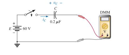
Fig. 10.109
Expert Solution & Answer
Want to see the full answer?
Check out a sample textbook solution
Students have asked these similar questions
120 *
8F
what is the T ?
b. what is the voitage capactor apter 10 sec?
c. How many
a.
time constants will it toake for tue
do Itage to reach 8o v.?
d. Given that the capacator is
Fully Charged, how
time constants will it be to reah
many
GOV
Exercise: What will be the o/p of the following meters?
F.W.R
H.W.R
D'Arsonval
Dynamo.
meter
PMMC
PMMC
meter
meter
meter
E=10V
1)
2)
3
1. A coil of 2000 turns with a 100-mA current has a length of 0.2 m. (a) Calculate
H in ampere-turns per
the mmf in ampere-turns. (b) Calculate the field intensity
meter.
Chapter 10 Solutions
Introductory Circuit Analysis (13th Edition)
Ch. 10 - a. Find the electric field strength at a point 1 m...Ch. 10 - The electric field strength is 72 newtons/coulomb...Ch. 10 - Find the capacitance of a parallel plate capacitor...Ch. 10 - How much charge is deposited on the plates of a...Ch. 10 - a. Find the electric field strength between the...Ch. 10 - A 6.8 pF parallel plate capacitor has 160 C of...Ch. 10 - Find the capacitance of a parallel plate capacitor...Ch. 10 - Repeat Problem 7 if the dielectric is...Ch. 10 - Find the distance in mils between the plates of a...Ch. 10 - The capacitance of a capacitor with a dielectric...
Ch. 10 - The plates of a parallel plate capacitor with a...Ch. 10 - A parallel plate air capacitor has a capacitance...Ch. 10 - Find the maximum voltage that can be applied...Ch. 10 - Find the distance in micrometers between the...Ch. 10 - A 22 pF capacitor has -200 ppm/C at room...Ch. 10 - What is the capacitance of a small teardrop...Ch. 10 - A large, flat, mica capacitor is labeled 471F....Ch. 10 - A small, flat, disc ceramic capacitor is labeled...Ch. 10 - For the circuit in Fig. 10.94, composed of...Ch. 10 - Repeat Problem 19 for R=100k, and compare the...Ch. 10 - For the circuit in Fig. 10.95, composed of...Ch. 10 - For the circuit in Fig. 10.96, composed of...Ch. 10 - Prob. 23PCh. 10 - The voltage across a 10 F capacitor in a series...Ch. 10 - For the R-C circuit in Fig. 10.97. composed of...Ch. 10 - For the network in Fig. 10.98. composed of...Ch. 10 - For the network in Fig.10.99.composed of standard...Ch. 10 - The 1000 F capacitor in Fig.10.100 is charged to...Ch. 10 - The capacitor in Fig. 10.101 is initially charged...Ch. 10 - Repeat Problem 29 if the initial charge is -40V.Ch. 10 - Repeat Problem 29 if the initial charge is +40V.Ch. 10 - The capacitor in Fig. 10.102 is initially charged...Ch. 10 - The capacitor in Fig. 10.103 is initially charged...Ch. 10 - The capacitor in Fig. 10.104 is initially charged...Ch. 10 - The capacitors of Fig. 10.105 are initially...Ch. 10 - Repeat Problem 35 if a 10 k resistor is placed in...Ch. 10 - Given the expression vc=140mV(1-e-t/2ms) a....Ch. 10 - For the automobile circuit of Fig. 10.106. VL must...Ch. 10 - Design the network in Fig.10.107 such that the...Ch. 10 - For the circuit in Fig. 10.108: a. Find the time...Ch. 10 - For the system in Fig. 10.109. using a DMM with a...Ch. 10 - For the circuit in Fig. 10.110: a. Find the...Ch. 10 - The capacitor in Fig. 10.111 is initially charged...Ch. 10 - The capacitors in Fig. 10.112 are initially...Ch. 10 - For the circuit in Fig. 10.113: a. Find the...Ch. 10 - The capacitor in Fig. 10.114 is initially charged...Ch. 10 - For the system in Fig. 10.115, using a DMM with a...Ch. 10 - Find the waveform for the average current if the...Ch. 10 - Find the waveform for the average current if the...Ch. 10 - Given the waveform in Fig.10.118 for the current...Ch. 10 - Find the total capacitance CT for the network in...Ch. 10 - Find the total capacitance CT for the network in...Ch. 10 - Find the steady-state voltage across and the...Ch. 10 - Find the steady-state voltage across and the...Ch. 10 - For the configuration in Fig. 10.123, determine...Ch. 10 - For the configuration in Fig.10.124, determine the...Ch. 10 - Find the energy stored by a 120 pF capacitor with...Ch. 10 - If the energy stored by a 6 F capacitor is 1200 J,...Ch. 10 - For the network in Fig. 10.125, determine the...Ch. 10 - An electronic flashgun has a 1000 F capacitor that...Ch. 10 - Using PSpice or Multisim, verify the results in...Ch. 10 - Using the initial condition operator, verify the...Ch. 10 - Using PSpice or Multisim, verify the results for...Ch. 10 - Using PSpice or Multisim, verify the results in...
Knowledge Booster


Learn more about
Need a deep-dive on the concept behind this application? Look no further. Learn more about this topic, electrical-engineering and related others by exploring similar questions and additional content below.Similar questions
- 9. Which of the following statements about conductivity is correct? Distilled water has a lower conductivity than salt water Distilled water has a higher conductivity than salt water Distilled water and salt water have zero conductivity O Distilled water and salt water have a similar conductivity Question 10 10. Which of the following measurements of conductivity is the highest? O 1.2 mS/cm 1100 μS/cm O 0.2 mS/cm O 12 µS/cmarrow_forwardCircuits 1 HW 7 Q4arrow_forwardQUESTION 1 If a multiratio CT having 150:5 CT ratio with 0.104 ohm secondary resistance and the excitation current 0.2 A, I -SA Za1 ohm. a) Find the primary side of the CT and show the details of your work. b) Find the CT error and show the details of your work.arrow_forward
- 4. With reference to the Paschen curve below, Breakdown voltage (V) 60 55 50 45 40 35 30 0.5 1.0 1.5 2.0 2.5 3.0 3.5 4.0 pd (cm-torr) If a discharge at p = 0.1 torr, d = 20 cm is to be initiated, what is the voltage required to cause a breakdown? What will be the breakdown voltage if p = 0.025 torr, d= 20 cm?arrow_forwardQuèstion 9 If a half wave rectifier is supplied using 240 V (rms), 50 Hz supply, then using constant voltage drop model, the average output voltage is equal to 107.8 V 108.04 V 152.79 V 76.17 V A Moving to another question will save this response. hparrow_forwardFind the following: (Please show complete solution) - Current after 3.3kohms resistor - Current after 1Okohms resistor - Current after 50kohms@50% variable resistor Given ans.: 720.825 µA, 512.396 µµA, 208.43 µA AIVIIVI II 720.825µA S9 R17 3.3k R18 10k 50% V9 www RP2 50k. RMM12 XMM13 LED LED1 1.497V 1.411Varrow_forward
- If you want to measure the current without breaking the circuit then which of the following meters is suitable clamp om meters Moving iron meter Moving coil meter electrodynamic metersarrow_forwardwww.resistorguide.com Temp. Coeff. (ppm/K) 250 (U) 100 (S) 50 (R) 15 (P) 25 (Q) 20 (Z) 10 (Z) 5 (M) 1(K) Color Signficant figures Multiply Tolerance Fail Rate (%) black x 1 x 10 x 100 x 1K х 10к x 100K x 1M x 10M x 100M х 1G x 0.1 x 0.01 Bad Вeer brown 1 (F) 2 (G) 0.1 0.01 Rots red 2. Our 3. orange yellow Young 4 0.001 0.5 (D) 0.25 (C) 0.1 (B) 0.05 (A) green blue Guts But 6. 6. 6. Vodka violet Goes 80 8. grey white gold silver Well 9. 9. 3th digit only for 5 and 6 bands 5 () 10 (K) 20 (M) Get Some Now! none 6 band 3.21kN 1% 50ppm/K 5 band 5212 1% 4 band 82kN 5% 3 band 3302 20% gap between band 3 and 4 indicates reading direction to their values. A. Enumerate the five (5) different types of resistors according to construction. Discuss the functions of each resistor. (include the actual picture of the component). Resistance Value First Color Second Color Third Color 100 2 620 0 1100 4 30 KO 19 KO B. Fill in the blanks with the values of the resistors corresponding to the colors. 300 0…arrow_forwardNeed Solution through half hr pleasearrow_forward
- 11. For the circuit below composed of standard values: • Determine the time constant. • Write the mathematical expression for the current i after the switch is closed. • Repeat part (b) for vL and vr • Determine i and vi at one, three, and five time constants. Sketch the waveforms of i, VL, and VR. + UR R 20 kN EE 40 V 470 mH UL llarrow_forwardHere are the choices: Lorentz law charge Faraday's law Ohm's law Capacitance Resistivity of materials Resistance vs Strainarrow_forwardAny simple example is fine.arrow_forward
arrow_back_ios
SEE MORE QUESTIONS
arrow_forward_ios
Recommended textbooks for you
 Introductory Circuit Analysis (13th Edition)Electrical EngineeringISBN:9780133923605Author:Robert L. BoylestadPublisher:PEARSON
 Delmar's Standard Textbook Of ElectricityElectrical EngineeringISBN:9781337900348Author:Stephen L. HermanPublisher:Cengage Learning
 Programmable Logic ControllersElectrical EngineeringISBN:9780073373843Author:Frank D. PetruzellaPublisher:McGraw-Hill Education
 Fundamentals of Electric CircuitsElectrical EngineeringISBN:9780078028229Author:Charles K Alexander, Matthew SadikuPublisher:McGraw-Hill Education
 Electric Circuits. (11th Edition)Electrical EngineeringISBN:9780134746968Author:James W. Nilsson, Susan RiedelPublisher:PEARSON
 Engineering ElectromagneticsElectrical EngineeringISBN:9780078028151Author:Hayt, William H. (william Hart), Jr, BUCK, John A.Publisher:Mcgraw-hill Education,
Introductory Circuit Analysis (13th Edition)
Electrical Engineering
ISBN:9780133923605
Author:Robert L. Boylestad
Publisher:PEARSON
Delmar's Standard Textbook Of Electricity
Electrical Engineering
ISBN:9781337900348
Author:Stephen L. Herman
Publisher:Cengage Learning
Programmable Logic Controllers
Electrical Engineering
ISBN:9780073373843
Author:Frank D. Petruzella
Publisher:McGraw-Hill Education
Fundamentals of Electric Circuits
Electrical Engineering
ISBN:9780078028229
Author:Charles K Alexander, Matthew Sadiku
Publisher:McGraw-Hill Education
Electric Circuits. (11th Edition)
Electrical Engineering
ISBN:9780134746968
Author:James W. Nilsson, Susan Riedel
Publisher:PEARSON
Engineering Electromagnetics
Electrical Engineering
ISBN:9780078028151
Author:Hayt, William H. (william Hart), Jr, BUCK, John A.
Publisher:Mcgraw-hill Education,
Current Divider Rule; Author: Neso Academy;https://www.youtube.com/watch?v=hRU1mKWUehY;License: Standard YouTube License, CC-BY