
Concept explainers
Videos
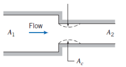
Flow through a sudden contraction is shown. The minimum flow area at the vena contracta is given in terms of the area ratio by the contraction coefficient [32],
The loss in a sudden contraction is mostly a result of the vena contracta: The fluid accelerates into the contraction, there is flow separation (as shown by the dashed lines), and the vena contracta acts as a miniature sudden expansion with significant secondary flow losses. Use these assumptions to obtain and plot estimates of the minor loss coefficient for a sudden contraction, and compare with the data presented in Fig. 8.15.
P8.81
Want to see the full answer?
Check out a sample textbook solution
Chapter 8 Solutions
Fox and McDonald's Introduction to Fluid Mechanics
Additional Engineering Textbook Solutions
Automotive Technology: Principles, Diagnosis, And Service (6th Edition) (halderman Automotive Series)
Thinking Like an Engineer: An Active Learning Approach (4th Edition)
Degarmo's Materials And Processes In Manufacturing
Statics and Mechanics of Materials (5th Edition)
Mechanics of Materials
Introduction to Heat Transfer


- 1. A pressure gauge attached to a pipe is reading 1.34 m of Hg at a place where the atmospheric pressure is 10.33 m of water. The approximate absolute pressure at the mountain isa. 930 kPab. 181 kPac. 280 kPad. 100 kPa 2. The flow is said to be unsteady and non-uniform when,a. The flow velocity is not changing with time but changing with spaceb. The flow velocity is changing with both time and spacec. The flow velocity is changing with time but not changing with spaced. The flow velocity is not changing with both time and space 3. The below figure shows a pipe with a circular cross section of diameter D mm on the left end and a square cross section with side D mm on the right end. Mercury enters the left end with a velocity 1 cm/s and leaves the right end with a velocity V2. Find V2 (neglect losses in the pipe).a. Cannot be find since length is not givenb. Cannot be find since diameter is not givenc. 7.85 mm/sd. 12.73 mm/s 4. 1 kg water is flowing through an inclined pipe at…arrow_forwardQ = Volume flow rate, μ= find, P= find E, the velocity of approach factor, can be calculated with E = 1/sqrt(1-B^4) E = 1 √1-B4 requires knowledge of the product CE. The beta ratio is ß = d0/d1 Then, the Reynolds number needs to be calculated: 4Q Red1 π * d₁ * v Where, v is the fluid kinematic viscosity And d1 is the circular pipes diameter.arrow_forwardCalculations involving retention time involve the following formula, T =, where V is volume and Q is flow rate. Often times, you will be required to calculate the volume of more than one tank and determine a rate of flow, given a total retention time. Tank 1 Tank 2 Let's assume that the total retention time for the entire system is 55 minutes, and we want to know the inlet flow, given the dimensions of tank 1 are : 14m x 10m x 3 m, and tank 2 are: 5m x 10m x 3 m. Calculate the inlet flow.arrow_forward
- Use g=32.2 */sec2 (9.81 m/s2) and 60°F (16°C) water unless told to do otherwise.• Google schedule-40 pipe’s thickness at different nominal size to obtain the innerdiameter of the pipe for accurate determinaLon of flow velocity.• Must show your work to support your selecLon. Otherwise, no points will be given.Water flows through a schedule-40 pipe that changes gradually in diameter from 6 in (154mm) at point A to 18 in (429 mm) at point B. The volumetric flow rate is 5.0 *3/sec (130 L/s). The respecLve pressures at points A and B are 10 psia (70 kPa) and 7 psia (48.3 kPa). All lossesare insignificant. What are the direcLon of flow and velocity at point A? (A) 3.2 */sec (1 m/s); from A to B(B) 25 */sec (7.0 m/s); from A to B(C) 3.2 */sec (1 m/s); from B to A(D) 25 */sec (7.5 m/s); from A to Barrow_forwardThree arterioles of the same length are in parallel and connected to an artery. The flow rate in the artery is 300 mL/min. One of the arterioles is constricted relative to the other two and has a flow rate of 50 mL/min. What is the flow rate in each of the other two arterioles? O 250 mL/min O It can't be determined unless you know the actual diameter and length of the arterioles 125 mL/min 300 mL/min 50 mL/minarrow_forwardQuestion 3 Consider 2 which shows a pipe system connecting two reservoirs. The pipe diameter changes at point B as shown in the image A 10 cm 23 m NOT TO SCALE Figure 2: 9 m 6 cm с 3 m 1. Describe what is referred to by the hydraulic gradient line and the energy gradient line. What is the difference between the two levels? In what scenario will the energy and hydraulic grade lines coincide? 2. Calculate the velocities in the two segments of the pipe. Take into account the friction losses through the pipe, entry loss to the pipe and the shock contraction losses at B. Take the pipe friction factor as 0.005 and the coefficient of contraction at B as 0.6. 3. Draw the energy gradient line and the hydraulic gradient line for the system.arrow_forward
- Flow takes place between three reservoirs, as shown in Figure 1. The volume flow rate out of reservoirs A and B is 0,15 m³/s and 0,25 m³/s respectively. If the coefficient of friction for three pipes is 0,008, determine the relative elevations of the free surfaces. Neglect all losses other than friction. May you kindly resend the answers in a different format as they appear blank??arrow_forward4. FLUID FLOW 1. The figure below shows a water tank with piping system for a small manufacturing plant. If water flows through the system ((A) at 40 L/s, what would be the pressure at point B? The water has a density of 998 kg per cubic meter and viscosity of 0.8 centipoise. measures 0.04089 m and 0.04826 m in inside and outside diameter, respectively. The tank is exposed to the atmosphere The 1.5 inches (nominal) wrought iron pipe Given: Q= 40L/s = 0.040 m/s p= 998 kg/m H=0.8 centipoise 0.001P-s = 0.08 P-S Reg'd: Pressure at B. = ? 1 cp i.d. = 0.04089 m o.d. = 0.04826 m length of pipe = 110 marrow_forwardIn a stationary fluid, The pressure head at same depth inside the fluid with decrease in density of liquid. O increases increases as well as decreases equal decreases Pitot tube is a discharge measuring device which measures exactly the quantity of fluid flowing in a pipe. Select one: True Falsearrow_forward
- A fan is used to blow air (density=1.15 kg/m3) in a duct. A pitot tube is placed in the duct as shown. The static pressure in the duct is measured with a wall tap and pressure gage. Use the gage readings to determine the velocity of the air. note: Pitot tube is used to measure the air total pressure. Mind on the head to be calculated if it is already in air. x 103 Pa Ptot tabe 12 x 103 Paarrow_forwardProblem 3. Outcome 5. Please show all work. Air at standard pressure but with T= 50°C flows through the ducting system shown in the figure. The gauge measures the pressure difference between the downstream and upstream points. All duct sections have circular cross section. Use the following geometry: D₁ = 60 mm, D, = 200 mm, L= 2 m. At this temperature, ai = 1.95 x 10⁻⁵ kg/m-s. Also recall that Rai = 287 J/kg-K. The center pipe is smooth with e0. Ap Voo D2 L D₁ Dz Figure for problem 3. The velocity entering the system, Voo; is measured to be 20 m/s. Estimate the Ap = Pdownstream Pupstream measured by the pressure gauge.arrow_forward*83. Go Two hoses are connected to the same outlet using a Y-connector, as the drawing shows. The hoses A and B have the same length, but hose B has the larger radius. Each is open to the atmosphere at the end where the water exits. Water flows through both hoses as a viscous fluid, and Poiseuille's law [Q = ™R°(P2 – P)/(8nL)] applies to each. In this law, , P, is the pressure upstream, P, is the pressure downstream, and Q is the volume flow rate. The ratio of the radius of hose B to the radius of hose A is Rg/RA = 1.50. Find the ratio of the speed of the water in hose B to the speed in hose A. Water from outlet Hose A Hose B Problem 83arrow_forward
 Elements Of ElectromagneticsMechanical EngineeringISBN:9780190698614Author:Sadiku, Matthew N. O.Publisher:Oxford University Press
 Mechanics of Materials (10th Edition)Mechanical EngineeringISBN:9780134319650Author:Russell C. HibbelerPublisher:PEARSON
 Thermodynamics: An Engineering ApproachMechanical EngineeringISBN:9781259822674Author:Yunus A. Cengel Dr., Michael A. BolesPublisher:McGraw-Hill Education
 Control Systems EngineeringMechanical EngineeringISBN:9781118170519Author:Norman S. NisePublisher:WILEY
 Mechanics of Materials (MindTap Course List)Mechanical EngineeringISBN:9781337093347Author:Barry J. Goodno, James M. GerePublisher:Cengage Learning
 Engineering Mechanics: StaticsMechanical EngineeringISBN:9781118807330Author:James L. Meriam, L. G. Kraige, J. N. BoltonPublisher:WILEY