
Videos
Consider fully developed laminar flow in the annulus between two concentric pipes. The outer pipe is stationary, and the inner pipe moves in the x direction with speed V. Assume the axial pressure gradient is zero (∂p/∂x = 0). Obtain a general expression for the shear stress, τ, as a function of the radius, r, in terms of a constant, C1. Obtain a general expression for the velocity profile, u(r), in terms of two constants, C1 and C2. Obtain expressions for C1 and C2.
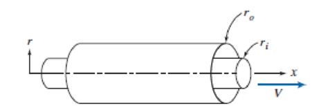
P8.36

Trending nowThis is a popular solution!

Chapter 8 Solutions
Fox and McDonald's Introduction to Fluid Mechanics
Additional Engineering Textbook Solutions
Engineering Mechanics: Statics
Applied Fluid Mechanics (7th Edition)
Manufacturing Engineering & Technology
Introduction to Heat Transfer
Statics and Mechanics of Materials (5th Edition)
Degarmo's Materials And Processes In Manufacturing


- A fluid has a kinematic viscosity ν=15x10-6 m2 s-1 and a density ρ=1 kg m-3. In a given industrial application we have a straight, circular pipe of radius 0.1 m and length 11.8 m. A pressure drop of Δp=4.8 Pa is imposed to drive the flow. Assuming a fully developed and steady state flow in the entire pipe, find the wall shear stress magnitude in SI units? Give your answer to three decimal places.arrow_forwardStudents conducted an experiment to evaluate the velocity profile,u(y), of a fluid flowing over a flat plate (Figure-3). Different students have reported different variations of velocity with vertical distance y from the plate as below. u(y)=y^2−2aby Obtain a relation of shear stress and wall shear stress in terms of a and b using the appropriate velocity profile. Calculate the shear stress at location y = 0.005 m, if the viscosity of the fluid is 60 Pa-s.arrow_forward4. Consider a viscous flow inside an annular pipe. The inner surface of the pipe is located at r = R₁ and is stationary. The outer surface is located at r = Ro and moves to the right with speed Upipe. The pressure inside the pipe is constant. The fluid inside the pipe has dynamic viscosity μ. Assume that the flow is steady, incompressible, fully-developed, axisymmetric, non-rotating, and has negligible body forces. Starting from the differential form of the conservation of mass and momentum equations: a. Derive an equation for the velocity inside the pipe in terms of Upipe, R₁, Ro, and r. b. Determine the average velocity inside the pipe in terms of Upipe, R₁, and Ro. C. Determine the shear stress acting on the inner annulus in terms of Upipe, Ri, Ro, and u. Upipe er R₁ fluidarrow_forward
- Your team is designing a chemical processing plant. You are the liquid handling and transportation specialist, and you need to transport a solvent (μ = 3.1 cP, ρ = 122k kg/m3) from a storage tank to a reaction vessel. Due to other equipment constraints, the fluid velocity must be 0.8 m/sec, and you must use stainless steel piping (ε = 0.00015 mm) with a total length (L) of 12 m. Determine the pipe inner diameter (ID) you will need to achieve a pressure drop of 0.3 kPa. Use the Moody chart.arrow_forwardProblem Consider a cylindrical pipe of length L and diameter D = 2R. The angle that the axis of the pipe forms with the vertical direction is a. Assume that when the fluid enters the pipe its velocity is uniform (i.e., it has the same value over the entire cross-section of the pipe) and equal to U in the axial direction. In the radial and angular directions, the velocity is zero. So, it is: 2 =0: v(r, 0, 2) = Ue, (1.1) Here v is the fluid velocity and e, is a vector of unit magnitude parallel to the coordinate axis z; furthermore, we have assumed that the pipe inlet is located at z = 0. Near the entrance of the pipe, the velocity profile varies in the axial direction. But after a certain entrance length, the profile becomes fully developed, no longer changing with z. The evolution of the velocity profile is sketched in Fig. 1, where, for clarity, the pipe inclination is not shown. The entrance length is denoted by L.. For z > L., the fluid velocity is no longer a function of the axial…arrow_forwardMethane gas is being pumped through a 305-m length of 52.5-mm-ID steel pipe at the rate of 41.0 kg/m2• s. The inlet pressure is P1 = 345 kPa abs. Assume isothermal flow at 288.8 K.a. Calculate the pressure P2 at the end of the pipe. The viscosity is 1.04 x 10 5 Pa·s.b. Calculate the maximum velocity that can be attained at these conditions and compare with the velocity in part (a).arrow_forward
- A smooth square cylinder is put in 15 °C flowing water. The flow direction is perpendicular to the long axis of the cylinder (parallel to the square section). The edge length of the square is s=2.0m. The long axis length is L=5.0m. The flow velocity is v=0.046 m/s. The density of water is ρ=1000kg/m3. T he dynamic viscosity is η=1.15×10⁻³kg/m·s. (2) Find the drag coefficient CD_________arrow_forwardA smooth square cylinder is put in 15 °C flowing water. The flow direction is perpendicular to the long axis of the cylinder (parallel to the square section). The edge length of the square is s=2.0m. The long axis length is L=5.0m. The flow velocity is v=0.046 m/s. The density of water is ρ=1000kg/m3. T he dynamic viscosity is η=1.15×10⁻³kg/m·s. (3) Calculate the drag force FD_________N (2 decimal places)arrow_forward5. A linear velocity profile is formed in a fluid between two plates as shown in the figure when one of the plates is moved parallel to the other and there is no externally imposed pressure gradient (i.e. there is no pump). If the top plate is travels at U = 0.3 m/s and the bottom plate is held fixed and the two plates are separated by a distance d = 0.3 m/s, derive an equation for the velocity profile u(y). Assume that the fluid in contact with either plate moves at the same speed as the plate (this is called the no-slip condition). U=0.3 m/s d=0.3 marrow_forward
- An incompressible Newtonian fluid having a thickness of h, flows steadily in the x- direction along a fixed wall of infinite extent by the influence of the gravitational force (g=9.81 m/s²). There is no pressure change in the flow direction and air friction is negligible. Using the given parameter values; a determine the velocity function, b. calculate the shear stress that will occur along the wall. Z fixed wall air h 0 16.0 ↓arrow_forwardAssume the following standard values if not provided with the problem statement • Air o p = 1.2 kg/m³ μ = 1.8 x 10⁻⁵ kg/(m s) • Water o p = 1000 kg/m³ o μ = 0.001 kg/(m s)arrow_forwardThe laminar flow of a fluid with viscosity µ and density ρ in a circular pipe of radius R has a velocity distribution described by where UCL is the velocity on the centerline where r = 0. (a) Using a control volume analysis, find τw, the shear stress at the wall, in terms of R and the pressure gradient dp/dx. (b) Using the expression for the velocity profile, find τw, the shear stress at the wall, in terms of µ, R, and UCL. (c) Find the average velocity in terms of UCL. (d) Using the results from parts (a)-(c), show that where Re is the Reynolds number based on the diameter D.arrow_forward
 Elements Of ElectromagneticsMechanical EngineeringISBN:9780190698614Author:Sadiku, Matthew N. O.Publisher:Oxford University Press
 Mechanics of Materials (10th Edition)Mechanical EngineeringISBN:9780134319650Author:Russell C. HibbelerPublisher:PEARSON
 Thermodynamics: An Engineering ApproachMechanical EngineeringISBN:9781259822674Author:Yunus A. Cengel Dr., Michael A. BolesPublisher:McGraw-Hill Education
 Control Systems EngineeringMechanical EngineeringISBN:9781118170519Author:Norman S. NisePublisher:WILEY
 Mechanics of Materials (MindTap Course List)Mechanical EngineeringISBN:9781337093347Author:Barry J. Goodno, James M. GerePublisher:Cengage Learning
 Engineering Mechanics: StaticsMechanical EngineeringISBN:9781118807330Author:James L. Meriam, L. G. Kraige, J. N. BoltonPublisher:WILEY