For pressure-driven, steady, fully developed laminar flow of an incompressible fluid through a straight channel of length L , we can define the hydraulic resistance as R hyd = Δ p / Q , where Δ p is the pressure drop and Q is the flow rate (analogous to the electrical resistance R elec = Δ V / I , where Δ V is the electrical potential drop and I is the electric current). The following table summarizes the hydraulic resistance of channels with different cross sectional shapes [30]: Calculate the hydraulic resistance of a straight channel with the listed cross-sectional shapes using the following parameters for water flow: μ = 1 mPa_s, L = 10 mm, a = 100 μ m, b = 33 μ m, h = 100 μ m, and w = 300 μ m. Based on the calculated hydraulic resistance, which shape is the most energy efficient to pump water?
For pressure-driven, steady, fully developed laminar flow of an incompressible fluid through a straight channel of length L , we can define the hydraulic resistance as R hyd = Δ p / Q , where Δ p is the pressure drop and Q is the flow rate (analogous to the electrical resistance R elec = Δ V / I , where Δ V is the electrical potential drop and I is the electric current). The following table summarizes the hydraulic resistance of channels with different cross sectional shapes [30]: Calculate the hydraulic resistance of a straight channel with the listed cross-sectional shapes using the following parameters for water flow: μ = 1 mPa_s, L = 10 mm, a = 100 μ m, b = 33 μ m, h = 100 μ m, and w = 300 μ m. Based on the calculated hydraulic resistance, which shape is the most energy efficient to pump water?
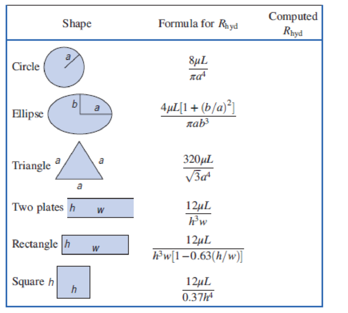
For pressure-driven, steady, fully developed laminar flow of an incompressible fluid through a straight channel of length L, we can define the hydraulic resistance as Rhyd = Δp/Q, where Δp is the pressure drop and Q is the flow rate (analogous to the electrical resistance Relec = ΔV/I, where ΔV is the electrical potential drop and I is the electric current). The following table summarizes the hydraulic resistance of channels with different cross sectional shapes [30]:
Calculate the hydraulic resistance of a straight channel with the listed cross-sectional shapes using the following parameters for water flow: μ = 1 mPa_s, L = 10 mm,a = 100 μm, b = 33 μm, h = 100μm, and w = 300 μm. Based on the calculated hydraulic resistance, which shape is the most energy efficient to pump water?
PP:PE
ميكانيك نضري محاضرة 15 .pdf
crease of the flowrate by a factor of
Qu, G tan(e/2) VTe (3H, A
On C, tan(a/2) VE (HYA
= 15.6
(Ans)
H.W1:Water flows steadily through the large tanks shown in fig.
below. What is the water depth, h, ?
Page 5
Northern Technical University
Technical college of Engineering / Mosul
Engineering Mechanics (II)(second year)
FIGURE P3.58
(1)
0.03 -m diameter
(2)
(3)
0.05 - m diameter
2 m
here
(4)
1. h,=50.4 m
2. h,=15.4 m
3. h,=5.4 m
4. h,-25.4
m.
H.W:What is the manometer reading, h, for the flow shown in fig.
below?
0.37
0.08 m
diametar
0.05 m diameter
1. h=0.73 m
2. h=0.54 m
3. h=0.25 m
4. h=0.37 m
H.W3: What is flowrate through the submerged orifice shown in fig.
below, if the contraction coefficient C,=0.63 ?
(1)
3dn.
diameter
1. Q=0.351 ft'is 2. Q=0.351 m'is 3. Q=0.451 ft'/s
fe'/s.
4. Q=0.351
Page 6
i need help with the calculations. i am messing up something in the math
The velocity distribution in a 0.02 m
diameter horizontal pipe conveying carbon
tetrachloride (specific gravity = 1.59,
absolute viscosity = 9.6 x 10⁻⁶ Pa sec) is
given by the parabolic equation:
v(r)=0.01(0.12- r?), where v(r) is the velocity
in (m/s) at a distance r in (m) from the pipe
center. What is discharge?
O a.
3.13 x-8 m3/s
O b. None of the mentioned
O c. 1.047 x 10⁸ m3/sec
O d. 4.97 x 10⁹ m3/sec
Chapter 8 Solutions
Fox and McDonald's Introduction to Fluid Mechanics
Starting Out with C++ from Control Structures to Objects (9th Edition)
Knowledge Booster
Learn more about
Need a deep-dive on the concept behind this application? Look no further. Learn more about this topic, mechanical-engineering and related others by exploring similar questions and additional content below.


 Elements Of ElectromagneticsMechanical EngineeringISBN:9780190698614Author:Sadiku, Matthew N. O.Publisher:Oxford University Press
 Mechanics of Materials (10th Edition)Mechanical EngineeringISBN:9780134319650Author:Russell C. HibbelerPublisher:PEARSON
 Thermodynamics: An Engineering ApproachMechanical EngineeringISBN:9781259822674Author:Yunus A. Cengel Dr., Michael A. BolesPublisher:McGraw-Hill Education
 Control Systems EngineeringMechanical EngineeringISBN:9781118170519Author:Norman S. NisePublisher:WILEY
 Mechanics of Materials (MindTap Course List)Mechanical EngineeringISBN:9781337093347Author:Barry J. Goodno, James M. GerePublisher:Cengage Learning
 Engineering Mechanics: StaticsMechanical EngineeringISBN:9781118807330Author:James L. Meriam, L. G. Kraige, J. N. BoltonPublisher:WILEY