
Videos
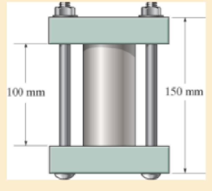
The 50-mm-diameter cylinder is made from Am 1004-T61 magnesium and is placed in the clamp when the temperature is T1=15°C. If the two 304-stainless-steel carriage bolts of the clamp each have a diameter of 10 mm. and they hold the cylinder snug with negligible force against the rigid jaws, determine the temperature at which the average normal stress in either the magnesium or the steel first becomes 12 MPa.

Learn your wayIncludes step-by-step video

Chapter 4 Solutions
Mechanics of Materials
Additional Engineering Textbook Solutions
Thinking Like an Engineer: An Active Learning Approach (4th Edition)
Automotive Technology: Principles, Diagnosis, and Service (5th Edition)
Automotive Technology: Principles, Diagnosis, And Service (6th Edition) (halderman Automotive Series)
Engineering Mechanics: Statics & Dynamics (14th Edition)
Engineering Mechanics: Dynamics (14th Edition)
Thinking Like an Engineer: An Active Learning Approach (3rd Edition)


- The assembly consists of two A992 steel bolts AB and EF and an 6061-T6 aluminum rod CD. When the temperature is at 30° C, the gap between the rod and rigid member AE is 0.1 mm. Determine the normal stress developed in the bolts and the rod if the temperature rises to 130° C. Assume BF is also rigid.arrow_forwardThe aluminum shell is fully bonded to the brass core and the assembly is unstressed at a temperature of 15°C. Considering only axial defor-mations, determine the stress in the aluminum when the temperature reaches 195°C.arrow_forwardThe gas storage tank is fabricated by bolting together two half cylindrical thin shells and two hemispherical shells as shown. If the tank is designed to withstand a pressure of 3 MPa, determine the required minimum thickness of the cylinder and hemispherical shells and the minimum required number of bolts for each hemispherical cap. The tank and the 25 mm diameter bolts are made from material having an allowable normal stress of 150 MPa and 250 MPa, respectively. The tank has an inner diameter of 4 m.arrow_forward
- The assembly has the diameters and material indicated. If it fits securely between its fixed supports when the temperature is T1 = 70°F, determine the average normal stress in each material when the temperature reaches T2 = 110°F.arrow_forward5. The rigid bar is supported by a smooth pin and two rods as shown. Neglect the weight of the rigid bar. The assembly is initially stress-free. Determine the stress in each rod if the temperature increases by 25°C after a load W = 100 kN is applied. The steel rod has an area of 320 mm² with a = 11.7 µm/ (m°C) and E = 200 GPa. For the bronze rod, it has an area of 1380 mm² with a = 18.9 μm/ ( mºC) and E = 83 GPa. Bronze 3 m Steel 1.5 m 1.0 m - O k 2.5 m 1.5 m W 6. Three wires are used to support the 150-lb force. The wires AB and AC are made of steel, and wire AD is made of copper. Assume that the three wires have constant cross-sectional area A = 0.0123 in². For steel wire, a = 8 x 10⁶ in/ (inºF) and E = 29000 ksi and for copper wire, a = 9.6 x 10⁻⁶ in/ (inºF) and E = 17000 ksi. Calculate the axial force exerted by the three wires if the temperature is raised by 80°F. Answer: Pst = 10 lb, Pcu = 136 lb B D 40 in. 60 in. 45°-45° 60 in. A 150 lbarrow_forwardThe steel bracket is used to connect the ends of two cables. If the allowable normal stress for the steel is sallow = 30 ksi, determine the largest tensile force P that can be applied to the cables. Assume the bracket is a rod havinga diameter of 1.5 in.arrow_forward
- The rigid bar ABCD of negligible weight is initially horizontal, and the steel rods attached at A and C are stress-free. If the temperature is dropped to −40°F and the 20-kip load is then applied, determine the stress in each steel rod at A and C Use E=29x106 psi and ∝=6.5x10⁻⁶/° F for steel.arrow_forward8-23. The plug has a diameter of 30 mm and fits within a rigid sleeve having an inner diameter of 32 mm. Both the plug and the sleeve are 50 mm long. Determine the axial pressure p that must be applied to the top of the plug to cause it to contact the sides of the sleeve. Alsa, how far must the plug be compressed downward in order to do this? The plug is made from a material for which E-5 MPa, v -0.45.arrow_forwardThe small-block has a thickness of 0.5 in. If the stress distribution at the support developed by the load varies as shown, determine the force F applied to the block, and the distance d to where it is applied.arrow_forward
- The 10-mm-diameter steel bolt is surrounded by a bronze sleeve. The outer diameter of this sleeve is 20 mm, and its inner diameter is 10 mm. If the bolt is subjected to a compressive force of P = 20 kN, determine the average normal stress in the steel and the bronze. Est = 200 GPa, Ebr = 100 GPa.arrow_forwardThe d = 15-mm-diameter solid rod passes through a D = 20-mm-diameter hole in the support plate. When a load P is applied to the rod, the rod head rests on the support plate. The support plate has a thickness of b = 15 mm. The rod head has a diameter of a = 30 mm, and the head has a thickness of t = 9 mm. If the normal stress produced in the rod by load P is 200 MPa, determine (a) the bearing stress acting between the support plate and the rod head. (b) the average shear stress produced in the rod head. (c) the punching shear stress produced in the support plate by the rod head. Support Plate Hole diameter D Rod Head Calculate the cross-sectional area of the rod. Answer: Arodi mm²arrow_forwardThe d = 13-mm-diameter solid rod passes through a D=21-mm-diameter hole in the support plate. When a load P is applied to the rod, the rod head rests on the support plate. The support plate has a thickness of b = 12 mm. The rod head has a diameter of a = 28 mm, and the head has a thickness of t = 8 mm. If the normal stress produced in the rod by load P is 150 MPa, determine (a) the bearing stress acting between the support plate and the rod head. (b) the average shear stress produced in the rod head. (c) the punching shear stress produced in the support plate by the rod head. Support Plate Hole diameter D Rod Head b Calculate the cross-sectional area of the rod. Answer: Arod mm²arrow_forward
 Elements Of ElectromagneticsMechanical EngineeringISBN:9780190698614Author:Sadiku, Matthew N. O.Publisher:Oxford University Press
 Mechanics of Materials (10th Edition)Mechanical EngineeringISBN:9780134319650Author:Russell C. HibbelerPublisher:PEARSON
 Thermodynamics: An Engineering ApproachMechanical EngineeringISBN:9781259822674Author:Yunus A. Cengel Dr., Michael A. BolesPublisher:McGraw-Hill Education
 Control Systems EngineeringMechanical EngineeringISBN:9781118170519Author:Norman S. NisePublisher:WILEY
 Mechanics of Materials (MindTap Course List)Mechanical EngineeringISBN:9781337093347Author:Barry J. Goodno, James M. GerePublisher:Cengage Learning
 Engineering Mechanics: StaticsMechanical EngineeringISBN:9781118807330Author:James L. Meriam, L. G. Kraige, J. N. BoltonPublisher:WILEY