
Introductory Circuit Analysis (13th Edition)
13th Edition
ISBN: 9780133923605
Author: Robert L. Boylestad
Publisher: PEARSON
expand_more
expand_more
format_list_bulleted
Concept explainers
Videos
Textbook Question
Chapter 6, Problem 9P
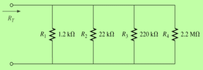
For the parallel network in Fig. 6.72, composed of standard values:
- Which resistor has the most impact on the total resistance?
- Without making a single calculation, what is an approximate value for the total resistance?
- Calculate the total resistance, and comment on your response to part (b).
- On an approximate basis, which resistors can be ignored when determining the total resistance?
- If we add another parallel resistor of any value to the network, what is the impact on the total resistance?
Expert Solution & Answer
Want to see the full answer?
Check out a sample textbook solution
Students have asked these similar questions
Show and COMPLETE solutions. Draw all CIRCUIT DIAGRAMS or the equivalent circuit (dummy circuit) as the case may be.
A battery is to consist of 20 identical cells. The emf of each cell is 1.5 V and the internal resistance is 0.20 ohm. This battery will be used to supply power to a 10-ohm lamp. Determine thecurrent on the lamp if:
The 20 cells are arranged 5 cells in series in 4 parallel rows.
INSTRUCTIONS: Solve the following problems. Show and COMPLETE solutions. Draw all CIRCUIT DIAGRAMS or the equivalent circuit (dummy circuit) as the case may be. Write your solutions on sheet/s of short bond paper.
A battery is to consist of 20 identical cells. The emf of each cell is 1.5 V and the internal resistance is 0.20 ohm. This battery will be used to supply power to a 10 ohm lamp. Determine the current on the lamp if:1. The 20 cells are connected in series 2. The 20 cells are connected in parallel 3. The 20 cells are arranged 5 cells in series in 4 parallel rows.
To measure the change in resistance of the gage(s) and indicate the location of the gauge on the beam, construct the Wheatstone bridge circuit. Calculate the Wheatstone bridge output if the gauge indicates a strain of 4000.then,Evaluate how can the number of strain gauges affects your measurement result. Justify your response with a calculation and a diagram showing the gage's placement on the beam.
Chapter 6 Solutions
Introductory Circuit Analysis (13th Edition)
Ch. 6 - For each configuration in Fig. 6.64, find the...Ch. 6 - For each configuration of Fig. 6.65, �nd the...Ch. 6 - For the network in Fig. 6.66: Find the elements...Ch. 6 - Find the total resistance for each configuration...Ch. 6 - Find the total resistance for each configuration...Ch. 6 - For each circuit board in Fig. 6.69, �nd the...Ch. 6 - The total resistance of each of the configurations...Ch. 6 - The total resistance for each configuration of...Ch. 6 - For the parallel network in Fig. 6.72, composed of...Ch. 6 - What is the ohmmeter reading for each...
Ch. 6 - Determine R1 for the network in Fig. 6.749.Ch. 6 - For the parallel network in Fig. 6.75: Find the...Ch. 6 - For the network of Fig. 6.76: Find the current...Ch. 6 - Repeat the analysis of Problem 13 for the network...Ch. 6 - For the parallel network in Fig. 6.78: Without...Ch. 6 - Given the information provided in Fig. 6.79, find:...Ch. 6 - Use the information in Fig. 6.80, to calculate:...Ch. 6 - Given the information provided in Fig. 6.81, find...Ch. 6 - For the network of Fig. 6.82, find: The voltage V....Ch. 6 - Using the information provided in Fig. 6.83 find:...Ch. 6 - For the network in Fig. 6.77: Redraw the network...Ch. 6 - For the configuration in Fig. 6.84: Find the total...Ch. 6 - Eight holiday lights are connected in parallel as...Ch. 6 - Determine the power delivered by the dc battery in...Ch. 6 - A portion of a residential service to a home is...Ch. 6 - For the network in Fig. 6.88: Find the current l1....Ch. 6 - Using Kirchhoffs current law, determine the...Ch. 6 - Using Kirchoffs current law, find the unknown...Ch. 6 - Using Kirchhoffs current law, determine the...Ch. 6 - Using the information provided in Fig. 6.92, find...Ch. 6 - Find the unknown quantities for the networks in...Ch. 6 - Find the unknown quantities for the networks of...Ch. 6 - Based solely on the resistor values, determine all...Ch. 6 - Determine one of the unknown currents of Fig....Ch. 6 - For each network of Fig. 6.97, determine the...Ch. 6 - Parts (a) through (e) of this problem should be...Ch. 6 - Find the unknown quantities for the networks in...Ch. 6 - Find resistance R for the network in Fig. 6.100...Ch. 6 - Design the network in Fig. 6.101 such that I2=2I1...Ch. 6 - Assuming identical supplies in Fig. 6.102: Find...Ch. 6 - Assuming identical supplies, determine currents...Ch. 6 - Assuming identical supplies, determine the current...Ch. 6 - For the simple series con�guration in Fig....Ch. 6 - Given the configuration in Fig. 6.106: What is the...Ch. 6 - Based on the measurements of Fig. 6.107, determine...Ch. 6 - Referring to Fig. 6.108, find the voltage Vab...Ch. 6 - The voltage Va for the network in Fig. 6.109, is...Ch. 6 - Prob. 48PCh. 6 - Using PSpice or Multisim, determine the solution...Ch. 6 - Using PSpice or Multisim, determine the solution...
Additional Engineering Textbook Solutions
Find more solutions based on key concepts
Identify the type of input and output configuration for each diff-amp in Figure 18-35.
Electronics Fundamentals: Circuits, Devices & Applications
The voltage source of the circuit shown in Fig. P1.29 is given by s(t)=25cos(4104t45)(V). Obtain an expression ...
Fundamentals of Applied Electromagnetics (7th Edition)
For the “tank” circuit in Fig. 14.79, find the resonant frequency.
Figure 14.79
For Probs. 14.39, 14.71, and 1...
Fundamentals of Electric Circuits
Three point charges of equal magnitude q, that will yield a zero net electric field at the origin.
Engineering Electromagnetics
Assume a telephone signal travels through a cable at two-thirds the speed of light. How long does it take the s...
Electric Circuits (10th Edition)
With respect to the circuit in Fig. 5.90, (a) employ Thévenin’s theorem to determine the equivalent network see...
Loose Leaf for Engineering Circuit Analysis Format: Loose-leaf
Knowledge Booster


Learn more about
Need a deep-dive on the concept behind this application? Look no further. Learn more about this topic, electrical-engineering and related others by exploring similar questions and additional content below.Similar questions
- a) Two or more resistors in a circuit are said to be in parallel when all the resistors are connected to the same nodes and the same voltage is appearing across all these elements. Two or more resistors in a circuit are also said to be in series when the current flowing through all the resistors is the same. With the aid of three resistors,4Ohm’s law and diagrams derive the two important total resistance formulas for the two connections to verify these two postulates b) Using your formulations in (a), find the current in the Load Resistor RL of resistance 30Ω and Thevenin’s resistance Rth of Figure 4 below. c) Find the resistance Req shown in the circuit in Figure 4 below using your knowledge of parallel and series connections demonstrated in (a)arrow_forwardFind the total resistance of the CKT Consider R = 1ohmarrow_forwardMAKE OBSERVATIONS AND ANALYSES FOR PARALLEL CONNECTED RESISTANCESarrow_forward
- 1. a) Design a combination circuit that has four LED’s and one resistor. Each LED will be in parallel and have its own switch. The circuit will have a resistor in series with the LED’s while they are connected in parallel. Each LED’s will drop 1.4vDC in parallel, with the same specifications. Make sure you size R1 (resistor R1) correctly using a VT of 9v. Each LED branch will have 20mA of current through it. Calculate all values including power at each component. b) Also, if the 9v battery had a rating of 2 watt-hours, how long would it last? If you wanted to make each LED 1/3 brighter than the other in parallel, how would you change the circuit to make that happen? Explain and show calculations. (Hint… you do not need transistor(s), but you can use them in your design).arrow_forwardThe resistances of four resistors are 2, 3, 5 and 8 ohms connected across 12 volts battery. The first tworesistances and the last two are connected in parallel which is in series to one another. Find : a) Draw the schematic diagram of the circuit and label b) the total resistance of the circuit c) the total current of the circuitarrow_forwardSolve the equivalent resistance across: a.) "a" and "b" b.) "b and "d"arrow_forward
- 4. Differentiate between the accuracy of the Wheatstone bridge and Kelvin Double bridge for the respective resistance measurement. 5. Signify the bridge to be used for the measurement of a test resistor having a value around 50 kQ? 6. In contrast, the unbalanced Wheatstone bridge is often used for measurement of different physical quantities. 6.1 Determine the condition(s) for unbalanced Wheatstone bridge 6.2 State and briefly explain what are physical quantities can be measured using an unbalanced Wheatstone bridge.arrow_forwardFor a set of resistors placed in parallel, the equivalent resistance is given by the sum of their individual resistance. a. true b. falsearrow_forwardAssuming you have a 6V battery and a 1.5V flashlight bulb which draws 0.5A when the bulb voltage is 1.5V. Design a network of resistors to go between the battery and the bulb to give VS=1.5V when the bulb is connected yet ensures that VS does not rise above 2V when the bulb is disconnected,,arrow_forward
- Draw a schematic (circuit) diagram of four resistors connected to a source (EMF) , where should have the same current with the total current in the circuit, while share this total amount of current at the same time. have the same values with the following color bands: red, black, red, gold; while also have the same values with the following color bands: yellow, violet, brown, gold. Applying the rules in series and parallel circuits as well as Ohm's law, discuss your complete solution conceptually and mathematically. In your own words, discuss comprehensively your strategic analysis on how to solve the problem. Show logical and systematic computations to solve for the unknowns. Present your evaluated data (final answers) in a tabular matrix. Express your final answers in two decimal places. Use the template below.arrow_forwardQ6// A resistance R is measured by the ammeter-voltmeter method. The voltmeter reading is 200 V and its internal resistance is 2K. If the ammeter reading is found to be 2A, what is the value of R ? aoarrow_forwardDraw a schematic of a circuit that converts the thermistor resistance to a measurable voltage. I suggest basing it on the only circuit you have studied so far: the voltage divider. Assuming that you have a negative-thermal coecient (NTC) thermistor and that you want higher temperature to result in higher voltage, which of the resistors in a voltage divider is the thermistor and which is a fixed resistor? Use the proper thermistor symbol and put the thermistor part number on the schematic. (For the final report, update this schematic with the resistor value chosen in the lab.)arrow_forward
arrow_back_ios
SEE MORE QUESTIONS
arrow_forward_ios
Recommended textbooks for you
 Introductory Circuit Analysis (13th Edition)Electrical EngineeringISBN:9780133923605Author:Robert L. BoylestadPublisher:PEARSON
 Delmar's Standard Textbook Of ElectricityElectrical EngineeringISBN:9781337900348Author:Stephen L. HermanPublisher:Cengage Learning
 Programmable Logic ControllersElectrical EngineeringISBN:9780073373843Author:Frank D. PetruzellaPublisher:McGraw-Hill Education
 Fundamentals of Electric CircuitsElectrical EngineeringISBN:9780078028229Author:Charles K Alexander, Matthew SadikuPublisher:McGraw-Hill Education
 Electric Circuits. (11th Edition)Electrical EngineeringISBN:9780134746968Author:James W. Nilsson, Susan RiedelPublisher:PEARSON
 Engineering ElectromagneticsElectrical EngineeringISBN:9780078028151Author:Hayt, William H. (william Hart), Jr, BUCK, John A.Publisher:Mcgraw-hill Education,
Introductory Circuit Analysis (13th Edition)
Electrical Engineering
ISBN:9780133923605
Author:Robert L. Boylestad
Publisher:PEARSON
Delmar's Standard Textbook Of Electricity
Electrical Engineering
ISBN:9781337900348
Author:Stephen L. Herman
Publisher:Cengage Learning
Programmable Logic Controllers
Electrical Engineering
ISBN:9780073373843
Author:Frank D. Petruzella
Publisher:McGraw-Hill Education
Fundamentals of Electric Circuits
Electrical Engineering
ISBN:9780078028229
Author:Charles K Alexander, Matthew Sadiku
Publisher:McGraw-Hill Education
Electric Circuits. (11th Edition)
Electrical Engineering
ISBN:9780134746968
Author:James W. Nilsson, Susan Riedel
Publisher:PEARSON
Engineering Electromagnetics
Electrical Engineering
ISBN:9780078028151
Author:Hayt, William H. (william Hart), Jr, BUCK, John A.
Publisher:Mcgraw-hill Education,
Current Divider Rule; Author: Neso Academy;https://www.youtube.com/watch?v=hRU1mKWUehY;License: Standard YouTube License, CC-BY