
Introductory Circuit Analysis (13th Edition)
13th Edition
ISBN: 9780133923605
Author: Robert L. Boylestad
Publisher: PEARSON
expand_more
expand_more
format_list_bulleted
Concept explainers
Videos
Textbook Question
Chapter 6, Problem 3P
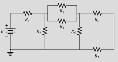
For the network in Fig. 6.66:
- Find the elements (individual voltage sources and/or resistors) that are in parallel.
- Find the elements (voltage sources and/or resistors) that are in series.
Expert Solution & Answer
Want to see the full answer?
Check out a sample textbook solution
Students have asked these similar questions
INSTRUCTIONS: Solve the following problems. Show and COMPLETE solutions. Draw all CIRCUIT DIAGRAMS or the equivalent circuit (dummy circuit) as the case may be. Write your solutions on sheet/s of short bond paper.
A battery is to consist of 20 identical cells. The emf of each cell is 1.5 V and the internal resistance is 0.20 ohm. This battery will be used to supply power to a 10 ohm lamp. Determine the current on the lamp if:1. The 20 cells are connected in series 2. The 20 cells are connected in parallel 3. The 20 cells are arranged 5 cells in series in 4 parallel rows.
Which of the following is/are an accurate statement/s?
A The potential in any closed loop is zero.
B In parallel connection of two resistors, the current is higher for lower resistance.
The voltage divider is used to find the potential across the resistors in parallel.
The sum of current entering the junction is equal to the sum of potential in any closed loop.
A battery is comprised of 6 cells connected in parallel, each cell has an EMF with 1.5V and an internal resistance of 0.50 ohm. There is a 4.6 ohm load connected to the terminals. Solve for VLoad.
Chapter 6 Solutions
Introductory Circuit Analysis (13th Edition)
Ch. 6 - For each configuration in Fig. 6.64, find the...Ch. 6 - For each configuration of Fig. 6.65, �nd the...Ch. 6 - For the network in Fig. 6.66: Find the elements...Ch. 6 - Find the total resistance for each configuration...Ch. 6 - Find the total resistance for each configuration...Ch. 6 - For each circuit board in Fig. 6.69, �nd the...Ch. 6 - The total resistance of each of the configurations...Ch. 6 - The total resistance for each configuration of...Ch. 6 - For the parallel network in Fig. 6.72, composed of...Ch. 6 - What is the ohmmeter reading for each...
Ch. 6 - Determine R1 for the network in Fig. 6.749.Ch. 6 - For the parallel network in Fig. 6.75: Find the...Ch. 6 - For the network of Fig. 6.76: Find the current...Ch. 6 - Repeat the analysis of Problem 13 for the network...Ch. 6 - For the parallel network in Fig. 6.78: Without...Ch. 6 - Given the information provided in Fig. 6.79, find:...Ch. 6 - Use the information in Fig. 6.80, to calculate:...Ch. 6 - Given the information provided in Fig. 6.81, find...Ch. 6 - For the network of Fig. 6.82, find: The voltage V....Ch. 6 - Using the information provided in Fig. 6.83 find:...Ch. 6 - For the network in Fig. 6.77: Redraw the network...Ch. 6 - For the configuration in Fig. 6.84: Find the total...Ch. 6 - Eight holiday lights are connected in parallel as...Ch. 6 - Determine the power delivered by the dc battery in...Ch. 6 - A portion of a residential service to a home is...Ch. 6 - For the network in Fig. 6.88: Find the current l1....Ch. 6 - Using Kirchhoffs current law, determine the...Ch. 6 - Using Kirchoffs current law, find the unknown...Ch. 6 - Using Kirchhoffs current law, determine the...Ch. 6 - Using the information provided in Fig. 6.92, find...Ch. 6 - Find the unknown quantities for the networks in...Ch. 6 - Find the unknown quantities for the networks of...Ch. 6 - Based solely on the resistor values, determine all...Ch. 6 - Determine one of the unknown currents of Fig....Ch. 6 - For each network of Fig. 6.97, determine the...Ch. 6 - Parts (a) through (e) of this problem should be...Ch. 6 - Find the unknown quantities for the networks in...Ch. 6 - Find resistance R for the network in Fig. 6.100...Ch. 6 - Design the network in Fig. 6.101 such that I2=2I1...Ch. 6 - Assuming identical supplies in Fig. 6.102: Find...Ch. 6 - Assuming identical supplies, determine currents...Ch. 6 - Assuming identical supplies, determine the current...Ch. 6 - For the simple series con�guration in Fig....Ch. 6 - Given the configuration in Fig. 6.106: What is the...Ch. 6 - Based on the measurements of Fig. 6.107, determine...Ch. 6 - Referring to Fig. 6.108, find the voltage Vab...Ch. 6 - The voltage Va for the network in Fig. 6.109, is...Ch. 6 - Prob. 48PCh. 6 - Using PSpice or Multisim, determine the solution...Ch. 6 - Using PSpice or Multisim, determine the solution...
Additional Engineering Textbook Solutions
Find more solutions based on key concepts
Does the severity of an electric shock increase ordecrease with eh of the following changes? a. A decrease in t...
Electric Motors and Control Systems
Analog Voltmeter Design Figure P2-98(a) shows a voltmeter circuit consisting of a D'Arsonval meter, two series ...
ANALYSIS+DESIGN OF LINEAR CIRCUITS(LL)
What is the color code for a 365- five-band precision resistor with a tolerance of 5 percent?
ELECTRICITY FOR TRADES (LOOSELEAF)
A constant voltage of 10V is applied to a 50H inductance, as shown in Figure P3.51 Figure P3 51 The current in ...
Electrical Engineering: Principles & Applications (7th Edition)
How many coulombs do 93.8 1016 electrons represent?
Principles Of Electric Circuits
The voltage source of the circuit shown in Fig. P1.29 is given by s(t)=25cos(4104t45)(V). Obtain an expression ...
Fundamentals of Applied Electromagnetics (7th Edition)
Knowledge Booster


Learn more about
Need a deep-dive on the concept behind this application? Look no further. Learn more about this topic, electrical-engineering and related others by exploring similar questions and additional content below.Similar questions
- Show and COMPLETE solutions. Draw all CIRCUIT DIAGRAMS or the equivalent circuit (dummy circuit) as the case may be. A battery is to consist of 20 identical cells. The emf of each cell is 1.5 V and the internal resistance is 0.20 ohm. This battery will be used to supply power to a 10-ohm lamp. Determine thecurrent on the lamp if: The 20 cells are arranged 5 cells in series in 4 parallel rows.arrow_forwardSolve for the circuits unknowns in the picture belowarrow_forwardA battery is comprised of 12 cells connected in series, each cell has an EMF with 1.4V and an internal resistance of 0.10 ohm. There is a 5.8 ohm load connected to the terminals. Solve for VLoad.arrow_forward
- Hiw Find the VR and ID for the following Circuits with drawing the charcteristic curve for each circuit. 65ol Vin 0.6 varrow_forward1. LED flashlights use "white" LEDs which have a diode voltage drop of 4.0V. An LED flashlight has the circuit illustrated and will run off of several AAA batteries that have a 1.5 VDC rating. a. What is the minimum number of AAA cells are needed to turn on the flashlight. 4/1.5 = 2.65 /3 b. Would you arrange the batteries in parallel or in series? Series a. What series resistor will give the specified LED current? (67 K 70 L b. What is the power dissipated by the resistor you selected in part a? Vdd fritzing 2. In the previous diagram for an LED circuit, the power supply is a 9V battery and we are using a Red LED whose voltage drop is 2V. The specification sheet for the LED recommends that the "ON" current should be 10 milliamps. c. What is the power dissipated in the LED? R + LED V 1arrow_forward1. a) Design a combination circuit that has four LED’s and one resistor. Each LED will be in parallel and have its own switch. The circuit will have a resistor in series with the LED’s while they are connected in parallel. Each LED’s will drop 1.4vDC in parallel, with the same specifications. Make sure you size R1 (resistor R1) correctly using a VT of 9v. Each LED branch will have 20mA of current through it. Calculate all values including power at each component. b) Also, if the 9v battery had a rating of 2 watt-hours, how long would it last? If you wanted to make each LED 1/3 brighter than the other in parallel, how would you change the circuit to make that happen? Explain and show calculations. (Hint… you do not need transistor(s), but you can use them in your design).arrow_forward
- To measure the change in resistance of the gage(s) and indicate the location of the gauge on the beam, construct the Wheatstone bridge circuit. Calculate the Wheatstone bridge output if the gauge indicates a strain of 4000.then,Evaluate how can the number of strain gauges affects your measurement result. Justify your response with a calculation and a diagram showing the gage's placement on the beam.arrow_forwardGive 5 example of parallel circuit found in homearrow_forwardSolve the voltage across 6.8-kohm resistor of the given circuit below. 32 V AGe 6.8 kohms 6 4 V O 35.7 V O 27.3 V O 35.3 V O 13.6 Varrow_forward
arrow_back_ios
SEE MORE QUESTIONS
arrow_forward_ios
Recommended textbooks for you
 Delmar's Standard Textbook Of ElectricityElectrical EngineeringISBN:9781337900348Author:Stephen L. HermanPublisher:Cengage Learning
Delmar's Standard Textbook Of Electricity
Electrical Engineering
ISBN:9781337900348
Author:Stephen L. Herman
Publisher:Cengage Learning
Kirchhoff's Rules of Electrical Circuits; Author: Flipping Physics;https://www.youtube.com/watch?v=d0O-KUKP4nM;License: Standard YouTube License, CC-BY