
Introductory Circuit Analysis (13th Edition)
13th Edition
ISBN: 9780133923605
Author: Robert L. Boylestad
Publisher: PEARSON
expand_more
expand_more
format_list_bulleted
Concept explainers
Videos
Textbook Question
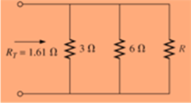
Chapter 6, Problem 7P
The total resistance of each of the configurations in Fig. 6.70, is specified. Find the unknown standard resistance value.
Expert Solution & Answer
Want to see the full answer?
Check out a sample textbook solution
Students have asked these similar questions
Which of the following is an accurate statement?
A Any principal node can be used as reference node.
B The potential between two principal nodes is zero.
C) The principal node is considered as lower potential with respect to reference node.
D There could be only one reference node in a given network.
5. A PMMC instrument gives 25mA at full scale reading when a potential difference across its terminals is 75mV. Show that how it can be used (a) as an ammeter for the current measurement in the range of 0-100A (b) as a 0 - 750V range voltmeter for the voltage measurement. Also, find the multiplying factor of shunt and voltage amplification.
The e.m.f. of a cell is balanced by the
length of 1.812 m of potentiometer wire, in the
potentiometer experiment. When a resistor of
5 ohms is connected across the cell, the
balancing length is found to be 1.51 m. Find
the internal resistance of the cell.
Chapter 6 Solutions
Introductory Circuit Analysis (13th Edition)
Ch. 6 - For each configuration in Fig. 6.64, find the...Ch. 6 - For each configuration of Fig. 6.65, �nd the...Ch. 6 - For the network in Fig. 6.66: Find the elements...Ch. 6 - Find the total resistance for each configuration...Ch. 6 - Find the total resistance for each configuration...Ch. 6 - For each circuit board in Fig. 6.69, �nd the...Ch. 6 - The total resistance of each of the configurations...Ch. 6 - The total resistance for each configuration of...Ch. 6 - For the parallel network in Fig. 6.72, composed of...Ch. 6 - What is the ohmmeter reading for each...
Ch. 6 - Determine R1 for the network in Fig. 6.749.Ch. 6 - For the parallel network in Fig. 6.75: Find the...Ch. 6 - For the network of Fig. 6.76: Find the current...Ch. 6 - Repeat the analysis of Problem 13 for the network...Ch. 6 - For the parallel network in Fig. 6.78: Without...Ch. 6 - Given the information provided in Fig. 6.79, find:...Ch. 6 - Use the information in Fig. 6.80, to calculate:...Ch. 6 - Given the information provided in Fig. 6.81, find...Ch. 6 - For the network of Fig. 6.82, find: The voltage V....Ch. 6 - Using the information provided in Fig. 6.83 find:...Ch. 6 - For the network in Fig. 6.77: Redraw the network...Ch. 6 - For the configuration in Fig. 6.84: Find the total...Ch. 6 - Eight holiday lights are connected in parallel as...Ch. 6 - Determine the power delivered by the dc battery in...Ch. 6 - A portion of a residential service to a home is...Ch. 6 - For the network in Fig. 6.88: Find the current l1....Ch. 6 - Using Kirchhoffs current law, determine the...Ch. 6 - Using Kirchoffs current law, find the unknown...Ch. 6 - Using Kirchhoffs current law, determine the...Ch. 6 - Using the information provided in Fig. 6.92, find...Ch. 6 - Find the unknown quantities for the networks in...Ch. 6 - Find the unknown quantities for the networks of...Ch. 6 - Based solely on the resistor values, determine all...Ch. 6 - Determine one of the unknown currents of Fig....Ch. 6 - For each network of Fig. 6.97, determine the...Ch. 6 - Parts (a) through (e) of this problem should be...Ch. 6 - Find the unknown quantities for the networks in...Ch. 6 - Find resistance R for the network in Fig. 6.100...Ch. 6 - Design the network in Fig. 6.101 such that I2=2I1...Ch. 6 - Assuming identical supplies in Fig. 6.102: Find...Ch. 6 - Assuming identical supplies, determine currents...Ch. 6 - Assuming identical supplies, determine the current...Ch. 6 - For the simple series con�guration in Fig....Ch. 6 - Given the configuration in Fig. 6.106: What is the...Ch. 6 - Based on the measurements of Fig. 6.107, determine...Ch. 6 - Referring to Fig. 6.108, find the voltage Vab...Ch. 6 - The voltage Va for the network in Fig. 6.109, is...Ch. 6 - Prob. 48PCh. 6 - Using PSpice or Multisim, determine the solution...Ch. 6 - Using PSpice or Multisim, determine the solution...
Additional Engineering Textbook Solutions
Find more solutions based on key concepts
When travelers from the USA and Canada visit Europe, they encounter a different power distribution system. Wall...
Electric machinery fundamentals
Design an ideal inverting op-amp circuit such that the voltage gain is Av=25 . The maximum current in any resis...
Microelectronics: Circuit Analysis and Design
The voltage source of the circuit shown in Fig. P1.29 is given by s(t)=25cos(4104t45)(V). Obtain an expression ...
Fundamentals of Applied Electromagnetics (7th Edition)
Does the severity of an electric shock increase ordecrease with eh of the following changes? a. A decrease in t...
Electric Motors and Control Systems
Find I0 and I1 in the circuit in Fig.P2.12.
Basic Engineering Circuit Analysis
Assume a telephone signal travels through a cable at two-thirds the speed of light. How long does it take the s...
Electric Circuits (10th Edition)
Knowledge Booster


Learn more about
Need a deep-dive on the concept behind this application? Look no further. Learn more about this topic, electrical-engineering and related others by exploring similar questions and additional content below.Similar questions
- Look at the images shown. Why can we measure resistance with a pencil drawn on a piece of paper? What is the component/material that is on the pencil that gives a high resistance? With the values given on the images, what are the corresponding color codes (indicate tolerance using a 4-band color code scheme)? If the first value is connected in series with the other value, what is the total resistance? If it’s parallel what is the total resistance? 0.449 mega ohms 102.2 kilo ohmsarrow_forwardPlease help me with this, attached herewith is the formula how to compute the range of expected resistance values for a known marked value. Give atleast 3 resistorsarrow_forwardA PMMC instrument has internal resistance of 0.77 ko and gives full scale deflection for 35 mA. The required resistance value of multiplier resistors for employing the meter as a multi range voltmeter for voltage range 79 V will be ohms. 102562.40 O 224.94 1487.14 O -326.96arrow_forward
- 4. From the figure shown which is series-parallel, the following values are: ID ohms in series with the parallel combination of 30 and DD ohms respectively. If the supply voltage is bD volts, find the following: a) equivalent resistance b)total current c)individual current d)current at 3D and D ohms onlyarrow_forward3) The resistance of semiconductor decreases with increase in temperature Select one: True Falsearrow_forwardAm ideal 6.0-V supply is connected to three resistors wired in parallel: R1= 12 ohms R2= 16 ohms and R3=1.0 K ohms. Calculate the equivalent circuit resistance, Find the current through the voltage supply and Determine the current through each resistor and the power consumed by each.arrow_forward
- A 9-Vdc battery is used in series with a 1-kQ, 100-µA to create a single range ohmmeter. Find the following: a. The series resistance b. The ohmmeter reading at half scalearrow_forwardThe graduation of the avometer to measure the resistances are...... to the real value. equal not equal none of the abovearrow_forwardTwo batteries, A and B, are connected in parallel and an 80 ohm resistor is connected across thebattery terminals. The e.m.f. and the internal resistance of battery A are l00V and 5 ohm respectively,and the corresponding values for battery B are 95V and 3 ohm respectively. Find (a) the value anddirection of the current in each battery and (b) the terminal voltagearrow_forward
- Problem No.2 group Six group of batteries are in parallel. Each has 10 cells connected in series, each has an internal emf of GV and resistance fo 0.412. a. Determine the equivalent emf and the internal resistance of the battery system.. b. If a 1-kn load resistor is connected to the battery system, what is the power dissipated to this load venistor? c. In & hre operation, determine the total energy delivered source to the 1-ks load resistor. the byarrow_forwardA battery is comprised of 4 cells connected in parallel, each cell has an EMF with 1.2V and an internal resistance of 0.55 ohm. There is no load connected to the terminals. Solve for Vterm.arrow_forwardWhat is the function of the circuit? Answer in minimized sum of productsarrow_forward
arrow_back_ios
SEE MORE QUESTIONS
arrow_forward_ios
Recommended textbooks for you
 Introductory Circuit Analysis (13th Edition)Electrical EngineeringISBN:9780133923605Author:Robert L. BoylestadPublisher:PEARSON
 Delmar's Standard Textbook Of ElectricityElectrical EngineeringISBN:9781337900348Author:Stephen L. HermanPublisher:Cengage Learning
 Programmable Logic ControllersElectrical EngineeringISBN:9780073373843Author:Frank D. PetruzellaPublisher:McGraw-Hill Education
 Fundamentals of Electric CircuitsElectrical EngineeringISBN:9780078028229Author:Charles K Alexander, Matthew SadikuPublisher:McGraw-Hill Education
 Electric Circuits. (11th Edition)Electrical EngineeringISBN:9780134746968Author:James W. Nilsson, Susan RiedelPublisher:PEARSON
 Engineering ElectromagneticsElectrical EngineeringISBN:9780078028151Author:Hayt, William H. (william Hart), Jr, BUCK, John A.Publisher:Mcgraw-hill Education,
Introductory Circuit Analysis (13th Edition)
Electrical Engineering
ISBN:9780133923605
Author:Robert L. Boylestad
Publisher:PEARSON
Delmar's Standard Textbook Of Electricity
Electrical Engineering
ISBN:9781337900348
Author:Stephen L. Herman
Publisher:Cengage Learning
Programmable Logic Controllers
Electrical Engineering
ISBN:9780073373843
Author:Frank D. Petruzella
Publisher:McGraw-Hill Education
Fundamentals of Electric Circuits
Electrical Engineering
ISBN:9780078028229
Author:Charles K Alexander, Matthew Sadiku
Publisher:McGraw-Hill Education
Electric Circuits. (11th Edition)
Electrical Engineering
ISBN:9780134746968
Author:James W. Nilsson, Susan Riedel
Publisher:PEARSON
Engineering Electromagnetics
Electrical Engineering
ISBN:9780078028151
Author:Hayt, William H. (william Hart), Jr, BUCK, John A.
Publisher:Mcgraw-hill Education,
Kirchhoff's Rules of Electrical Circuits; Author: Flipping Physics;https://www.youtube.com/watch?v=d0O-KUKP4nM;License: Standard YouTube License, CC-BY