
Introductory Circuit Analysis (13th Edition)
13th Edition
ISBN: 9780133923605
Author: Robert L. Boylestad
Publisher: PEARSON
expand_more
expand_more
format_list_bulleted
Concept explainers
Videos
Textbook Question
Chapter 6, Problem 5P
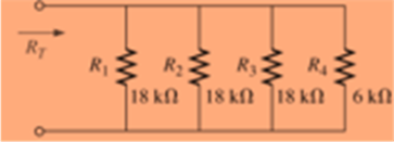
Find the total resistance for each configuration of Fig. 6.68. Note that only standard resistor values are included.
Expert Solution & Answer

Trending nowThis is a popular solution!

Students have asked these similar questions
A 9-Vdc battery is used in series with a 1-kQ, 100-µA to create a
single range ohmmeter. Find the following:
a. The series resistance
b. The ohmmeter reading at half scale
Look at the images shown. Why can we measure resistance with a pencil drawn on a piece of paper? What is the component/material that is on the pencil that gives a high resistance? With the values given on the images, what are the corresponding color codes (indicate tolerance using a 4-band color code scheme)? If the first value is connected in series with the other value, what is the total resistance? If it’s parallel what is the total resistance?
0.449 mega ohms
102.2 kilo ohms
Which of the following is/are an accurate statement/s?
A The potential in any closed loop is zero.
B In parallel connection of two resistors, the current is higher for lower resistance.
The voltage divider is used to find the potential across the resistors in parallel.
The sum of current entering the junction is equal to the sum of potential in any closed loop.
Chapter 6 Solutions
Introductory Circuit Analysis (13th Edition)
Ch. 6 - For each configuration in Fig. 6.64, find the...Ch. 6 - For each configuration of Fig. 6.65, �nd the...Ch. 6 - For the network in Fig. 6.66: Find the elements...Ch. 6 - Find the total resistance for each configuration...Ch. 6 - Find the total resistance for each configuration...Ch. 6 - For each circuit board in Fig. 6.69, �nd the...Ch. 6 - The total resistance of each of the configurations...Ch. 6 - The total resistance for each configuration of...Ch. 6 - For the parallel network in Fig. 6.72, composed of...Ch. 6 - What is the ohmmeter reading for each...
Ch. 6 - Determine R1 for the network in Fig. 6.749.Ch. 6 - For the parallel network in Fig. 6.75: Find the...Ch. 6 - For the network of Fig. 6.76: Find the current...Ch. 6 - Repeat the analysis of Problem 13 for the network...Ch. 6 - For the parallel network in Fig. 6.78: Without...Ch. 6 - Given the information provided in Fig. 6.79, find:...Ch. 6 - Use the information in Fig. 6.80, to calculate:...Ch. 6 - Given the information provided in Fig. 6.81, find...Ch. 6 - For the network of Fig. 6.82, find: The voltage V....Ch. 6 - Using the information provided in Fig. 6.83 find:...Ch. 6 - For the network in Fig. 6.77: Redraw the network...Ch. 6 - For the configuration in Fig. 6.84: Find the total...Ch. 6 - Eight holiday lights are connected in parallel as...Ch. 6 - Determine the power delivered by the dc battery in...Ch. 6 - A portion of a residential service to a home is...Ch. 6 - For the network in Fig. 6.88: Find the current l1....Ch. 6 - Using Kirchhoffs current law, determine the...Ch. 6 - Using Kirchoffs current law, find the unknown...Ch. 6 - Using Kirchhoffs current law, determine the...Ch. 6 - Using the information provided in Fig. 6.92, find...Ch. 6 - Find the unknown quantities for the networks in...Ch. 6 - Find the unknown quantities for the networks of...Ch. 6 - Based solely on the resistor values, determine all...Ch. 6 - Determine one of the unknown currents of Fig....Ch. 6 - For each network of Fig. 6.97, determine the...Ch. 6 - Parts (a) through (e) of this problem should be...Ch. 6 - Find the unknown quantities for the networks in...Ch. 6 - Find resistance R for the network in Fig. 6.100...Ch. 6 - Design the network in Fig. 6.101 such that I2=2I1...Ch. 6 - Assuming identical supplies in Fig. 6.102: Find...Ch. 6 - Assuming identical supplies, determine currents...Ch. 6 - Assuming identical supplies, determine the current...Ch. 6 - For the simple series con�guration in Fig....Ch. 6 - Given the configuration in Fig. 6.106: What is the...Ch. 6 - Based on the measurements of Fig. 6.107, determine...Ch. 6 - Referring to Fig. 6.108, find the voltage Vab...Ch. 6 - The voltage Va for the network in Fig. 6.109, is...Ch. 6 - Prob. 48PCh. 6 - Using PSpice or Multisim, determine the solution...Ch. 6 - Using PSpice or Multisim, determine the solution...
Knowledge Booster


Learn more about
Need a deep-dive on the concept behind this application? Look no further. Learn more about this topic, electrical-engineering and related others by exploring similar questions and additional content below.Similar questions
- Which of the following is an accurate statement? A Any principal node can be used as reference node. B The potential between two principal nodes is zero. C) The principal node is considered as lower potential with respect to reference node. D There could be only one reference node in a given network.arrow_forwardINSTRUCTIONS: Solve the following problems. Show and COMPLETE solutions. Draw all CIRCUIT DIAGRAMS or the equivalent circuit (dummy circuit) as the case may be. Write your solutions on sheet/s of short bond paper. A battery is to consist of 20 identical cells. The emf of each cell is 1.5 V and the internal resistance is 0.20 ohm. This battery will be used to supply power to a 10 ohm lamp. Determine the current on the lamp if:1. The 20 cells are connected in series 2. The 20 cells are connected in parallel 3. The 20 cells are arranged 5 cells in series in 4 parallel rows.arrow_forwardA PMMC instrument has internal resistance of 0.77 ko and gives full scale deflection for 35 mA. The required resistance value of multiplier resistors for employing the meter as a multi range voltmeter for voltage range 79 V will be ohms. 102562.40 O 224.94 1487.14 O -326.96arrow_forward
- a) (i)Write the classification of recorders. (ii) Draw the block diagram of strip chart recorder and label the blocks b)A PMMC instrument gives 15 mA at full scale reading when a potential difference across its terminals is 41mV. Show that how it can be used (i) as an ammeter for the current measurement in the range of 0-5 A (ii) as a 0 -620V range voltmeter for the voltage measurement. (iii) find the multiplying factor of shunt and (iv) voltage amplification Rsh shunt resistance R1 series resistance multiplying factor for current voltage amplificationarrow_forward1. LED flashlights use "white" LEDs which have a diode voltage drop of 4.0V. An LED flashlight has the circuit illustrated and will run off of several AAA batteries that have a 1.5 VDC rating. a. What is the minimum number of AAA cells are needed to turn on the flashlight. 4/1.5 = 2.65 /3 b. Would you arrange the batteries in parallel or in series? Series a. What series resistor will give the specified LED current? (67 K 70 L b. What is the power dissipated by the resistor you selected in part a? Vdd fritzing 2. In the previous diagram for an LED circuit, the power supply is a 9V battery and we are using a Red LED whose voltage drop is 2V. The specification sheet for the LED recommends that the "ON" current should be 10 milliamps. c. What is the power dissipated in the LED? R + LED V 1arrow_forwardCompute for the equivalent resistancearrow_forward
- Which of the following is an accurate statement? A There could be two or more reference node in a given network. (B The principal node is considered as lower potential with respect to reference node. Any principal node can be used as reference node. The potential between two principal nodes is zero.arrow_forwardFind the equivalent capacity between the points "a" and "b"arrow_forwardConsider a PV Module with 4 solar PV cells with the Size of each 10cm x 10cm are connected in Parallel. Choose the correct statement for the above PV Module. (Assume necessary data) a. The output voltage is 0.5 V, the output power is 12W b. The output voltage is 2 V, the output power is 12W c. The output voltage is 12 V, the output power is 6W d. The output voltage is 0.5 V, the output power is 6Warrow_forward
- A PMMC instrument gives 29 mA at full scale reading when a potential difference across its terminals is 41mV. Show that how it can be used (a) as an ammeter for the current measurement in the range of 0 –6.5 A (b) as a 0 – 790V range voltmeter for the voltage measurement. (c) find the multiplying factor of shunt and (d) voltage amplificationarrow_forward4. Differentiate between the accuracy of the Wheatstone bridge and Kelvin Double bridge for the respective resistance measurement. 5. Signify the bridge to be used for the measurement of a test resistor having a value around 50 kQ? 6. In contrast, the unbalanced Wheatstone bridge is often used for measurement of different physical quantities. 6.1 Determine the condition(s) for unbalanced Wheatstone bridge 6.2 State and briefly explain what are physical quantities can be measured using an unbalanced Wheatstone bridge.arrow_forwardExample (2): Design d.c voltmeter by using direct method with d'Arsonval meter of 1002 and full scale deflection of 100µA to give the following ranges: 10mV, 1V, and 100V.arrow_forward
arrow_back_ios
SEE MORE QUESTIONS
arrow_forward_ios
Recommended textbooks for you
 Introductory Circuit Analysis (13th Edition)Electrical EngineeringISBN:9780133923605Author:Robert L. BoylestadPublisher:PEARSON
 Delmar's Standard Textbook Of ElectricityElectrical EngineeringISBN:9781337900348Author:Stephen L. HermanPublisher:Cengage Learning
 Programmable Logic ControllersElectrical EngineeringISBN:9780073373843Author:Frank D. PetruzellaPublisher:McGraw-Hill Education
 Fundamentals of Electric CircuitsElectrical EngineeringISBN:9780078028229Author:Charles K Alexander, Matthew SadikuPublisher:McGraw-Hill Education
 Electric Circuits. (11th Edition)Electrical EngineeringISBN:9780134746968Author:James W. Nilsson, Susan RiedelPublisher:PEARSON
 Engineering ElectromagneticsElectrical EngineeringISBN:9780078028151Author:Hayt, William H. (william Hart), Jr, BUCK, John A.Publisher:Mcgraw-hill Education,
Introductory Circuit Analysis (13th Edition)
Electrical Engineering
ISBN:9780133923605
Author:Robert L. Boylestad
Publisher:PEARSON
Delmar's Standard Textbook Of Electricity
Electrical Engineering
ISBN:9781337900348
Author:Stephen L. Herman
Publisher:Cengage Learning
Programmable Logic Controllers
Electrical Engineering
ISBN:9780073373843
Author:Frank D. Petruzella
Publisher:McGraw-Hill Education
Fundamentals of Electric Circuits
Electrical Engineering
ISBN:9780078028229
Author:Charles K Alexander, Matthew Sadiku
Publisher:McGraw-Hill Education
Electric Circuits. (11th Edition)
Electrical Engineering
ISBN:9780134746968
Author:James W. Nilsson, Susan Riedel
Publisher:PEARSON
Engineering Electromagnetics
Electrical Engineering
ISBN:9780078028151
Author:Hayt, William H. (william Hart), Jr, BUCK, John A.
Publisher:Mcgraw-hill Education,
Kirchhoff's Rules of Electrical Circuits; Author: Flipping Physics;https://www.youtube.com/watch?v=d0O-KUKP4nM;License: Standard YouTube License, CC-BY