
Introductory Circuit Analysis (13th Edition)
13th Edition
ISBN: 9780133923605
Author: Robert L. Boylestad
Publisher: PEARSON
expand_more
expand_more
format_list_bulleted
Concept explainers
Videos
Textbook Question
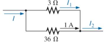
Chapter 6, Problem 37P
Find the unknown quantities for the networks in Fig. 6.99, using the information provided.
Expert Solution & Answer
Want to see the full answer?
Check out a sample textbook solution
Students have asked these similar questions
For the network in fig. 6.66
A.Find the elements (individual voltage sources and /or resistors) that are in parallel .
B. Find the elements (voltage sources and/or resistors) that are in series
جامعتا
Use the information in Fig. 6.80 to calculate:
2010
a. The source voltage E.
b. The resistance R2.
c. The current 11.
d. The source current Is.
e. The power supplied by the source.
f. The power supplied to the resistors R1 and R2.
g. Compare the power calculated in part (e) to the sum of
the power delivered to all the resistors.
E
R₁
14
· 12 Ω
3 A
R₂ R3
VER
P = 120 W
6Ω
Use information in fig .6.80 to calculate
A. The source voltage E
B.the resistance R2
c the current l1
D.the source current Is
E The power supplied by the source
F. The power supplied to the resistor R1 and R2
G. Compare the power calculated in part(e) to the sum of the power delivered to all the resistor.
Chapter 6 Solutions
Introductory Circuit Analysis (13th Edition)
Ch. 6 - For each configuration in Fig. 6.64, find the...Ch. 6 - For each configuration of Fig. 6.65, �nd the...Ch. 6 - For the network in Fig. 6.66: Find the elements...Ch. 6 - Find the total resistance for each configuration...Ch. 6 - Find the total resistance for each configuration...Ch. 6 - For each circuit board in Fig. 6.69, �nd the...Ch. 6 - The total resistance of each of the configurations...Ch. 6 - The total resistance for each configuration of...Ch. 6 - For the parallel network in Fig. 6.72, composed of...Ch. 6 - What is the ohmmeter reading for each...
Ch. 6 - Determine R1 for the network in Fig. 6.749.Ch. 6 - For the parallel network in Fig. 6.75: Find the...Ch. 6 - For the network of Fig. 6.76: Find the current...Ch. 6 - Repeat the analysis of Problem 13 for the network...Ch. 6 - For the parallel network in Fig. 6.78: Without...Ch. 6 - Given the information provided in Fig. 6.79, find:...Ch. 6 - Use the information in Fig. 6.80, to calculate:...Ch. 6 - Given the information provided in Fig. 6.81, find...Ch. 6 - For the network of Fig. 6.82, find: The voltage V....Ch. 6 - Using the information provided in Fig. 6.83 find:...Ch. 6 - For the network in Fig. 6.77: Redraw the network...Ch. 6 - For the configuration in Fig. 6.84: Find the total...Ch. 6 - Eight holiday lights are connected in parallel as...Ch. 6 - Determine the power delivered by the dc battery in...Ch. 6 - A portion of a residential service to a home is...Ch. 6 - For the network in Fig. 6.88: Find the current l1....Ch. 6 - Using Kirchhoffs current law, determine the...Ch. 6 - Using Kirchoffs current law, find the unknown...Ch. 6 - Using Kirchhoffs current law, determine the...Ch. 6 - Using the information provided in Fig. 6.92, find...Ch. 6 - Find the unknown quantities for the networks in...Ch. 6 - Find the unknown quantities for the networks of...Ch. 6 - Based solely on the resistor values, determine all...Ch. 6 - Determine one of the unknown currents of Fig....Ch. 6 - For each network of Fig. 6.97, determine the...Ch. 6 - Parts (a) through (e) of this problem should be...Ch. 6 - Find the unknown quantities for the networks in...Ch. 6 - Find resistance R for the network in Fig. 6.100...Ch. 6 - Design the network in Fig. 6.101 such that I2=2I1...Ch. 6 - Assuming identical supplies in Fig. 6.102: Find...Ch. 6 - Assuming identical supplies, determine currents...Ch. 6 - Assuming identical supplies, determine the current...Ch. 6 - For the simple series con�guration in Fig....Ch. 6 - Given the configuration in Fig. 6.106: What is the...Ch. 6 - Based on the measurements of Fig. 6.107, determine...Ch. 6 - Referring to Fig. 6.108, find the voltage Vab...Ch. 6 - The voltage Va for the network in Fig. 6.109, is...Ch. 6 - Prob. 48PCh. 6 - Using PSpice or Multisim, determine the solution...Ch. 6 - Using PSpice or Multisim, determine the solution...
Additional Engineering Textbook Solutions
Find more solutions based on key concepts
Identify the type of input and output configuration for each diff-amp in Figure 18-35.
Electronics Fundamentals: Circuits, Devices & Applications
How many coulombs do 93.8 1016 electrons represent?
Principles Of Electric Circuits
When travelers from the USA and Canada visit Europe, they encounter a different power distribution system. Wall...
Electric machinery fundamentals
With respect to the circuit in Fig. 5.90, (a) employ Thévenin’s theorem to determine the equivalent network see...
Loose Leaf for Engineering Circuit Analysis Format: Loose-leaf
The voltage source of the circuit shown in Fig. P1.29 is given by s(t)=25cos(4104t45)(V). Obtain an expression ...
Fundamentals of Applied Electromagnetics (7th Edition)
Analog Voltmeter Design Figure P2-98(a) shows a voltmeter circuit consisting of a D'Arsonval meter, two series ...
ANALYSIS+DESIGN OF LINEAR CIRCUITS(LL)
Knowledge Booster


Learn more about
Need a deep-dive on the concept behind this application? Look no further. Learn more about this topic, electrical-engineering and related others by exploring similar questions and additional content below.Similar questions
- Use the information in Fig. 6.80 to calculate: a. The source voltage E. b. The resistance R2. c. The current 11. d. The source current Is. e. The power supplied by the source. f. The power supplied to the resistors R1 and R2. g. Compare the power calculated in part (e) to the sum of the power delivered to all the resistors. مع E + Is 14 12 02 3 A R₂ R3 P = 120 W 6Ωarrow_forwardPROBLEMS I 237 c. Calculate the power delivered by the source. d. Compare the power delivered by the source to the sum of the powers delivered to the resistors. e. Which resistor received the most power? Why? 20. Eight holiday lights are connected in parallel as shown in Fig. 6.89. a. If the set is connected to a 120 V source, what is the cur- rent through each bulb if each bulb has an internal resis- tance of 1.8 kN? b. Determine the total resistance of the network. c. Find the current drain from the supply. d. What is the power delivered to each bulb? e. Using the results of part (d), find the power delivered b the source. f. If one bulb burns out (that is, the filament opens ut what is the effect on the remaining bulbs? What is effect on the source current? Why? FIG. 6.89 Problem 20.arrow_forward6.19 For the network shown determine: a) the voltage V ; b) the current I,; c) the current I, ; d) power in 12kn , 12 κΩ 18 kN 48 V + v 3 kNarrow_forward
- For the network in Fig. 6.88:a. Find the current I1.b. Calculate the power dissipated by the 4 Ω resistor.c. Find the current I2.arrow_forward6:06 A e-learning.hct.edu.om Question: A group of Students from UTAS (Physics Unit) visit Al Hassan Electrical laboratory. Their supervisor gives them instruction about use of Resistors in different electrical appliances. Students are provided with four resistors R,=50 ohm, R2=70 ohm, R3=380 ohm, R4=70 ohm and a battery of 40 v. i) If students connect these four resistances in series, what is the effective resistance? ii) If students connect these four resistances in parallel, what is the effective resistance? iii) If students connect 40 V battery across series combination, what is the current flowing in the circuit? iv) If students connect 40 V battery across parallel combination, what is the current flowing in the circuit? v) If students connect these four resistances shown below, what is the voltage across points a and d? R2 R1 R4 b. R3 V Finish attempt...arrow_forwardSECTION 6.6 Current Divider Rule * L'sing the information provided in Fig. 6.88, determine the uren tirough each branch using simply the ratio of nar. alle' resistor values. Then determine the total current I, sing the current divider rule. find the unknown currents for the nerworks of Fig. 6.89. 12 4. 20 4 40 1 FIG. 6.88 Problem 22. 12 A 6A (a) (b) 500 mA 12 0 20 18 N = 4A (c) (d) FIG. 6.89 Problem 23.arrow_forward
- 16. Given the information provided in Fig. 6.79, find: a. The resistance R₂. b. The supply voltage E. RT=802 P=64 W R₁200R₂ FIG. 6.79 Problem 16.arrow_forwardKindly write the node voltage equations for Fig. 6.11.arrow_forwardEXAMPLE Tam ekrandan çıkmak iç Determine the following for the network of Fig. 6.26. (a) Ip, and Voso (6) Vos (c) V (d) Vs Ioun-9 mA T--3 V R1.5k2 F-10 Varrow_forward
- 20. Using the information provided in Fig. 6.86, find te branch resistors R1 and R3, the total resistance R7, and he voltage source E. 9 mA 5 mA 2 mA R2 4 kN R FIG. 6.86 Problem 20.arrow_forward14. Using the information provided, determine the resistance R, for the network of Fig. 6.80. *15. Determine the power delivered by the de battery in Fig. 6.81. 50 6 A 60 V E+ 12 V R, 10N 20 2 FIG. 6.80 FIG. 6.81 Problem 14. Problem 15.arrow_forward15. Determine the power delivered by the de battery in Fig. 6.81. 60 V 10n 20 0 FIG. 6.81 Problem 15.arrow_forward
arrow_back_ios
SEE MORE QUESTIONS
arrow_forward_ios
Recommended textbooks for you
 Introductory Circuit Analysis (13th Edition)Electrical EngineeringISBN:9780133923605Author:Robert L. BoylestadPublisher:PEARSON
 Delmar's Standard Textbook Of ElectricityElectrical EngineeringISBN:9781337900348Author:Stephen L. HermanPublisher:Cengage Learning
 Programmable Logic ControllersElectrical EngineeringISBN:9780073373843Author:Frank D. PetruzellaPublisher:McGraw-Hill Education
 Fundamentals of Electric CircuitsElectrical EngineeringISBN:9780078028229Author:Charles K Alexander, Matthew SadikuPublisher:McGraw-Hill Education
 Electric Circuits. (11th Edition)Electrical EngineeringISBN:9780134746968Author:James W. Nilsson, Susan RiedelPublisher:PEARSON
 Engineering ElectromagneticsElectrical EngineeringISBN:9780078028151Author:Hayt, William H. (william Hart), Jr, BUCK, John A.Publisher:Mcgraw-hill Education,
Introductory Circuit Analysis (13th Edition)
Electrical Engineering
ISBN:9780133923605
Author:Robert L. Boylestad
Publisher:PEARSON
Delmar's Standard Textbook Of Electricity
Electrical Engineering
ISBN:9781337900348
Author:Stephen L. Herman
Publisher:Cengage Learning
Programmable Logic Controllers
Electrical Engineering
ISBN:9780073373843
Author:Frank D. Petruzella
Publisher:McGraw-Hill Education
Fundamentals of Electric Circuits
Electrical Engineering
ISBN:9780078028229
Author:Charles K Alexander, Matthew Sadiku
Publisher:McGraw-Hill Education
Electric Circuits. (11th Edition)
Electrical Engineering
ISBN:9780134746968
Author:James W. Nilsson, Susan Riedel
Publisher:PEARSON
Engineering Electromagnetics
Electrical Engineering
ISBN:9780078028151
Author:Hayt, William H. (william Hart), Jr, BUCK, John A.
Publisher:Mcgraw-hill Education,
Kirchhoff's Rules of Electrical Circuits; Author: Flipping Physics;https://www.youtube.com/watch?v=d0O-KUKP4nM;License: Standard YouTube License, CC-BY