
Introductory Circuit Analysis (13th Edition)
13th Edition
ISBN: 9780133923605
Author: Robert L. Boylestad
Publisher: PEARSON
expand_more
expand_more
format_list_bulleted
Concept explainers
Videos
Textbook Question
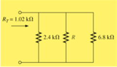
Chapter 6, Problem 8P
The total resistance for each configuration of Fig. 6.71, is specified. Find the unknown resistance level. All unknowns are standard values.
Expert Solution & Answer

Trending nowThis is a popular solution!

Students have asked these similar questions
Which of the following is an accurate statement?
A Any principal node can be used as reference node.
B The potential between two principal nodes is zero.
C) The principal node is considered as lower potential with respect to reference node.
D There could be only one reference node in a given network.
A battery with EMF of 6V and an internal resistance, r= 0.65 ohms is connected to a load resistance R=58 ohms. Determine its terminal voltage.
A battery is comprised of 7 cells connected in parallel, each cell has an EMF with 1.4V and an internal resistance of 0.55 ohm. There is a 5.8 ohm load connected to the terminals. Solve for ILoad.
Chapter 6 Solutions
Introductory Circuit Analysis (13th Edition)
Ch. 6 - For each configuration in Fig. 6.64, find the...Ch. 6 - For each configuration of Fig. 6.65, �nd the...Ch. 6 - For the network in Fig. 6.66: Find the elements...Ch. 6 - Find the total resistance for each configuration...Ch. 6 - Find the total resistance for each configuration...Ch. 6 - For each circuit board in Fig. 6.69, �nd the...Ch. 6 - The total resistance of each of the configurations...Ch. 6 - The total resistance for each configuration of...Ch. 6 - For the parallel network in Fig. 6.72, composed of...Ch. 6 - What is the ohmmeter reading for each...
Ch. 6 - Determine R1 for the network in Fig. 6.749.Ch. 6 - For the parallel network in Fig. 6.75: Find the...Ch. 6 - For the network of Fig. 6.76: Find the current...Ch. 6 - Repeat the analysis of Problem 13 for the network...Ch. 6 - For the parallel network in Fig. 6.78: Without...Ch. 6 - Given the information provided in Fig. 6.79, find:...Ch. 6 - Use the information in Fig. 6.80, to calculate:...Ch. 6 - Given the information provided in Fig. 6.81, find...Ch. 6 - For the network of Fig. 6.82, find: The voltage V....Ch. 6 - Using the information provided in Fig. 6.83 find:...Ch. 6 - For the network in Fig. 6.77: Redraw the network...Ch. 6 - For the configuration in Fig. 6.84: Find the total...Ch. 6 - Eight holiday lights are connected in parallel as...Ch. 6 - Determine the power delivered by the dc battery in...Ch. 6 - A portion of a residential service to a home is...Ch. 6 - For the network in Fig. 6.88: Find the current l1....Ch. 6 - Using Kirchhoffs current law, determine the...Ch. 6 - Using Kirchoffs current law, find the unknown...Ch. 6 - Using Kirchhoffs current law, determine the...Ch. 6 - Using the information provided in Fig. 6.92, find...Ch. 6 - Find the unknown quantities for the networks in...Ch. 6 - Find the unknown quantities for the networks of...Ch. 6 - Based solely on the resistor values, determine all...Ch. 6 - Determine one of the unknown currents of Fig....Ch. 6 - For each network of Fig. 6.97, determine the...Ch. 6 - Parts (a) through (e) of this problem should be...Ch. 6 - Find the unknown quantities for the networks in...Ch. 6 - Find resistance R for the network in Fig. 6.100...Ch. 6 - Design the network in Fig. 6.101 such that I2=2I1...Ch. 6 - Assuming identical supplies in Fig. 6.102: Find...Ch. 6 - Assuming identical supplies, determine currents...Ch. 6 - Assuming identical supplies, determine the current...Ch. 6 - For the simple series con�guration in Fig....Ch. 6 - Given the configuration in Fig. 6.106: What is the...Ch. 6 - Based on the measurements of Fig. 6.107, determine...Ch. 6 - Referring to Fig. 6.108, find the voltage Vab...Ch. 6 - The voltage Va for the network in Fig. 6.109, is...Ch. 6 - Prob. 48PCh. 6 - Using PSpice or Multisim, determine the solution...Ch. 6 - Using PSpice or Multisim, determine the solution...
Additional Engineering Textbook Solutions
Find more solutions based on key concepts
Assume a telephone signal travels through a cable at two-thirds the speed of light. How long does it take the s...
Electric Circuits (10th Edition)
A constant voltage of 10V is applied to a 50H inductance, as shown in Figure P3.51 Figure P3 51 The current in ...
Electrical Engineering: Principles & Applications (7th Edition)
Does the severity of an electric shock increase ordecrease with eh of the following changes? a. A decrease in t...
Electric Motors and Control Systems
Analog Voltmeter Design Figure P2-98(a) shows a voltmeter circuit consisting of a D'Arsonval meter, two series ...
ANALYSIS+DESIGN OF LINEAR CIRCUITS(LL)
Find I0 and I1 in the circuit in Fig.P2.12.
Basic Engineering Circuit Analysis
The current source in the circuit shown generates the current pulse
Find (a) v (0); (b) the instant of time gr...
Electric Circuits. (11th Edition)
Knowledge Booster


Learn more about
Need a deep-dive on the concept behind this application? Look no further. Learn more about this topic, electrical-engineering and related others by exploring similar questions and additional content below.Similar questions
- Which of the following is an accurate statement? A There could be two or more reference node in a given network. (B The principal node is considered as lower potential with respect to reference node. Any principal node can be used as reference node. The potential between two principal nodes is zero.arrow_forward6:06 A e-learning.hct.edu.om Question: A group of Students from UTAS (Physics Unit) visit Al Hassan Electrical laboratory. Their supervisor gives them instruction about use of Resistors in different electrical appliances. Students are provided with four resistors R,=50 ohm, R2=70 ohm, R3=380 ohm, R4=70 ohm and a battery of 40 v. i) If students connect these four resistances in series, what is the effective resistance? ii) If students connect these four resistances in parallel, what is the effective resistance? iii) If students connect 40 V battery across series combination, what is the current flowing in the circuit? iv) If students connect 40 V battery across parallel combination, what is the current flowing in the circuit? v) If students connect these four resistances shown below, what is the voltage across points a and d? R2 R1 R4 b. R3 V Finish attempt...arrow_forwardLook at the images shown. Why can we measure resistance with a pencil drawn on a piece of paper? What is the component/material that is on the pencil that gives a high resistance? With the values given on the images, what are the corresponding color codes (indicate tolerance using a 4-band color code scheme)? If the first value is connected in series with the other value, what is the total resistance? If it’s parallel what is the total resistance? 0.449 mega ohms 102.2 kilo ohmsarrow_forward
- For the network in fig. 6.66 A.Find the elements (individual voltage sources and /or resistors) that are in parallel . B. Find the elements (voltage sources and/or resistors) that are in seriesarrow_forward6:03 A e-learning.hct.edu.om Four resistors R1=190 ohm, R2=330 ohm, R3=330 ohm and R4=50 ohm are connected to a 36 V battery as shown in the diagram below. R1 a V R3 R2 R4 i) What is the effective resistance of the circuit? ii) What is the reading of ammeter? iii) What is the voltage across R1 (between the points a and b)? iv) What is the voltage across R2 and R3 (between the points b and c)? v) What is the voltage across R4 (between the points c and d)?arrow_forwardA 9-Vdc battery is used in series with a 1-kQ, 100-µA to create a single range ohmmeter. Find the following: a. The series resistance b. The ohmmeter reading at half scalearrow_forward
- A PMMC instrument has internal resistance of 0.77 ko and gives full scale deflection for 35 mA. The required resistance value of multiplier resistors for employing the meter as a multi range voltmeter for voltage range 79 V will be ohms. 102562.40 O 224.94 1487.14 O -326.96arrow_forwardCreate a circuit diagram using the instructions given then find its Requivalent.arrow_forwardP/ calculate the effective resisfance of the following combination of vesistance between pomts A and B then find veltage drop across each resistance when BD of 6ov is appliad between Puints A and B Aarrow_forward
- Using the value of R, calculate the total resistance which is the resistance between terminals X and Y. (LET R= 6.234) (SHOW COMPLETE SOLUTION AND PLS WRITE CLEARLY)arrow_forwardA battery is comprised of 4 cells connected in parallel, each cell has an EMF with 1.4V and an internal resistance of 0.50 ohm. There is no load connected to the terminals. Solve for Et.arrow_forwarda) (i)Write the classification of recorders. (ii) Draw the block diagram of strip chart recorder and label the blocks b)A PMMC instrument gives 15 mA at full scale reading when a potential difference across its terminals is 41mV. Show that how it can be used (i) as an ammeter for the current measurement in the range of 0-5 A (ii) as a 0 -620V range voltmeter for the voltage measurement. (iii) find the multiplying factor of shunt and (iv) voltage amplification Rsh shunt resistance R1 series resistance multiplying factor for current voltage amplificationarrow_forward
arrow_back_ios
SEE MORE QUESTIONS
arrow_forward_ios
Recommended textbooks for you
 Introductory Circuit Analysis (13th Edition)Electrical EngineeringISBN:9780133923605Author:Robert L. BoylestadPublisher:PEARSON
 Delmar's Standard Textbook Of ElectricityElectrical EngineeringISBN:9781337900348Author:Stephen L. HermanPublisher:Cengage Learning
 Programmable Logic ControllersElectrical EngineeringISBN:9780073373843Author:Frank D. PetruzellaPublisher:McGraw-Hill Education
 Fundamentals of Electric CircuitsElectrical EngineeringISBN:9780078028229Author:Charles K Alexander, Matthew SadikuPublisher:McGraw-Hill Education
 Electric Circuits. (11th Edition)Electrical EngineeringISBN:9780134746968Author:James W. Nilsson, Susan RiedelPublisher:PEARSON
 Engineering ElectromagneticsElectrical EngineeringISBN:9780078028151Author:Hayt, William H. (william Hart), Jr, BUCK, John A.Publisher:Mcgraw-hill Education,
Introductory Circuit Analysis (13th Edition)
Electrical Engineering
ISBN:9780133923605
Author:Robert L. Boylestad
Publisher:PEARSON
Delmar's Standard Textbook Of Electricity
Electrical Engineering
ISBN:9781337900348
Author:Stephen L. Herman
Publisher:Cengage Learning
Programmable Logic Controllers
Electrical Engineering
ISBN:9780073373843
Author:Frank D. Petruzella
Publisher:McGraw-Hill Education
Fundamentals of Electric Circuits
Electrical Engineering
ISBN:9780078028229
Author:Charles K Alexander, Matthew Sadiku
Publisher:McGraw-Hill Education
Electric Circuits. (11th Edition)
Electrical Engineering
ISBN:9780134746968
Author:James W. Nilsson, Susan Riedel
Publisher:PEARSON
Engineering Electromagnetics
Electrical Engineering
ISBN:9780078028151
Author:Hayt, William H. (william Hart), Jr, BUCK, John A.
Publisher:Mcgraw-hill Education,
Kirchhoff's Rules of Electrical Circuits; Author: Flipping Physics;https://www.youtube.com/watch?v=d0O-KUKP4nM;License: Standard YouTube License, CC-BY