
Introductory Circuit Analysis (13th Edition)
13th Edition
ISBN: 9780133923605
Author: Robert L. Boylestad
Publisher: PEARSON
expand_more
expand_more
format_list_bulleted
Concept explainers
Videos
Textbook Question
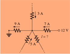
Chapter 6, Problem 28P
Using Kirchoff’s current law, find the unknown currents for the complex configurations in Fig. 6.90.
Expert Solution & Answer
Want to see the full answer?
Check out a sample textbook solution
Students have asked these similar questions
For the network in fig. 6.66
A.Find the elements (individual voltage sources and /or resistors) that are in parallel .
B. Find the elements (voltage sources and/or resistors) that are in series
A battery is comprised of 7 cells connected in parallel, each cell has an EMF with 1.4V and an internal resistance of 0.55 ohm. There is a 5.8 ohm load connected to the terminals. Solve for ILoad.
A battery is comprised of 4 cells connected in parallel, each cell has an EMF with 1.4V and an internal resistance of 0.50 ohm. There is no load connected to the terminals. Solve for Et.
Chapter 6 Solutions
Introductory Circuit Analysis (13th Edition)
Ch. 6 - For each configuration in Fig. 6.64, find the...Ch. 6 - For each configuration of Fig. 6.65, �nd the...Ch. 6 - For the network in Fig. 6.66: Find the elements...Ch. 6 - Find the total resistance for each configuration...Ch. 6 - Find the total resistance for each configuration...Ch. 6 - For each circuit board in Fig. 6.69, �nd the...Ch. 6 - The total resistance of each of the configurations...Ch. 6 - The total resistance for each configuration of...Ch. 6 - For the parallel network in Fig. 6.72, composed of...Ch. 6 - What is the ohmmeter reading for each...
Ch. 6 - Determine R1 for the network in Fig. 6.749.Ch. 6 - For the parallel network in Fig. 6.75: Find the...Ch. 6 - For the network of Fig. 6.76: Find the current...Ch. 6 - Repeat the analysis of Problem 13 for the network...Ch. 6 - For the parallel network in Fig. 6.78: Without...Ch. 6 - Given the information provided in Fig. 6.79, find:...Ch. 6 - Use the information in Fig. 6.80, to calculate:...Ch. 6 - Given the information provided in Fig. 6.81, find...Ch. 6 - For the network of Fig. 6.82, find: The voltage V....Ch. 6 - Using the information provided in Fig. 6.83 find:...Ch. 6 - For the network in Fig. 6.77: Redraw the network...Ch. 6 - For the configuration in Fig. 6.84: Find the total...Ch. 6 - Eight holiday lights are connected in parallel as...Ch. 6 - Determine the power delivered by the dc battery in...Ch. 6 - A portion of a residential service to a home is...Ch. 6 - For the network in Fig. 6.88: Find the current l1....Ch. 6 - Using Kirchhoffs current law, determine the...Ch. 6 - Using Kirchoffs current law, find the unknown...Ch. 6 - Using Kirchhoffs current law, determine the...Ch. 6 - Using the information provided in Fig. 6.92, find...Ch. 6 - Find the unknown quantities for the networks in...Ch. 6 - Find the unknown quantities for the networks of...Ch. 6 - Based solely on the resistor values, determine all...Ch. 6 - Determine one of the unknown currents of Fig....Ch. 6 - For each network of Fig. 6.97, determine the...Ch. 6 - Parts (a) through (e) of this problem should be...Ch. 6 - Find the unknown quantities for the networks in...Ch. 6 - Find resistance R for the network in Fig. 6.100...Ch. 6 - Design the network in Fig. 6.101 such that I2=2I1...Ch. 6 - Assuming identical supplies in Fig. 6.102: Find...Ch. 6 - Assuming identical supplies, determine currents...Ch. 6 - Assuming identical supplies, determine the current...Ch. 6 - For the simple series con�guration in Fig....Ch. 6 - Given the configuration in Fig. 6.106: What is the...Ch. 6 - Based on the measurements of Fig. 6.107, determine...Ch. 6 - Referring to Fig. 6.108, find the voltage Vab...Ch. 6 - The voltage Va for the network in Fig. 6.109, is...Ch. 6 - Prob. 48PCh. 6 - Using PSpice or Multisim, determine the solution...Ch. 6 - Using PSpice or Multisim, determine the solution...
Additional Engineering Textbook Solutions
Find more solutions based on key concepts
Explain the main function of each of the following major components of a PLC: a. Processor module (CPU) b. I/O ...
Programmable Logic Controllers
Identify the type of input and output configuration for each diff-amp in Figure 18-35.
Electronics Fundamentals: Circuits, Devices & Applications
When travelers from the USA and Canada visit Europe, they encounter a different power distribution system. Wall...
Electric machinery fundamentals
How many coulombs do 93.8 1016 electrons represent?
Principles Of Electric Circuits
Three point charges of equal magnitude q, that will yield a zero net electric field at the origin.
Engineering Electromagnetics
Design an ideal inverting op-amp circuit such that the voltage gain is Av=25 . The maximum current in any resis...
Microelectronics: Circuit Analysis and Design
Knowledge Booster


Learn more about
Need a deep-dive on the concept behind this application? Look no further. Learn more about this topic, electrical-engineering and related others by exploring similar questions and additional content below.Similar questions
- A 150V moving iron volt meter intended for 50Hz has an inductance of 0.7H and a resistance of 3K ohm. Find the series resistance required to extend the range of instrument to 300V if this 300V - 50Hz instrument used to measure dc voltage find the dc voltage when the scale reading is 200Varrow_forwardA resistance of 12 ohms and capacitance of 0.01 farad is connected in series with a 200 volts battery. Find the charge after 0.5 second and the current after 0.4 secondarrow_forward6:03 A e-learning.hct.edu.om Four resistors R1=190 ohm, R2=330 ohm, R3=330 ohm and R4=50 ohm are connected to a 36 V battery as shown in the diagram below. R1 a V R3 R2 R4 i) What is the effective resistance of the circuit? ii) What is the reading of ammeter? iii) What is the voltage across R1 (between the points a and b)? iv) What is the voltage across R2 and R3 (between the points b and c)? v) What is the voltage across R4 (between the points c and d)?arrow_forward
- 6,9,12 ohm..... solve it correctly. i will rate accordingly.arrow_forward6:06 A e-learning.hct.edu.om Question: A group of Students from UTAS (Physics Unit) visit Al Hassan Electrical laboratory. Their supervisor gives them instruction about use of Resistors in different electrical appliances. Students are provided with four resistors R,=50 ohm, R2=70 ohm, R3=380 ohm, R4=70 ohm and a battery of 40 v. i) If students connect these four resistances in series, what is the effective resistance? ii) If students connect these four resistances in parallel, what is the effective resistance? iii) If students connect 40 V battery across series combination, what is the current flowing in the circuit? iv) If students connect 40 V battery across parallel combination, what is the current flowing in the circuit? v) If students connect these four resistances shown below, what is the voltage across points a and d? R2 R1 R4 b. R3 V Finish attempt...arrow_forwardCan you explain this problem to me and help me though it? thank you for the helparrow_forward
- In the simulation, which of the following statements correctly compare the ideal parallel plate capacitor to the ideal solenoid. Select all that applyarrow_forwarda) Find the value of x if the equivalent capacitance between point a and b is 6 microfarad b) Also find the voltage across x if it has a charge of +2 Coulomb on one of its platarrow_forwardDesign a DC voltage source to maintain fixed, stable 15 V, 13.6 V and 12.2 V DC voltages to different loads. In order to realize this request, a transformer having a primer voltage 220 V AC and a seconder voltage 27 V AC (220/27 V AC transformer), some silicon diodes, zener diode and some resistors of 1.5 k2 can be considered in design. a) Draw the network b) Explain the tasks of each component and overall operation in your design. c) Calculate load current and power dissipation for zener diodearrow_forward
- Given the information provided in Fig. 6.24: a. Determine R3. b. Find the applied voltage E. c. Find the source current Is. d. Find 12. E RT=402 JH R₁ 1₁ = 4A 10 Ω R₂ 12 20 N R3 www +arrow_forward3. A 45 uF capacitor and a 30 uF capacitor are connected in parallel to a 25 V battery. What is the total capacitance of the circuit? b. What is the voltage, V, across capacitor, C,? c. What is the voltage, V, across capacitor, C? d. How much charge, Q, is on capacitor, C,? How much charge, Q2, is on capacitor, C,? a. e.arrow_forwardKindly write the node voltage equations for Fig. 6.11.arrow_forward
arrow_back_ios
SEE MORE QUESTIONS
arrow_forward_ios
Recommended textbooks for you
 Introductory Circuit Analysis (13th Edition)Electrical EngineeringISBN:9780133923605Author:Robert L. BoylestadPublisher:PEARSON
 Delmar's Standard Textbook Of ElectricityElectrical EngineeringISBN:9781337900348Author:Stephen L. HermanPublisher:Cengage Learning
 Programmable Logic ControllersElectrical EngineeringISBN:9780073373843Author:Frank D. PetruzellaPublisher:McGraw-Hill Education
 Fundamentals of Electric CircuitsElectrical EngineeringISBN:9780078028229Author:Charles K Alexander, Matthew SadikuPublisher:McGraw-Hill Education
 Electric Circuits. (11th Edition)Electrical EngineeringISBN:9780134746968Author:James W. Nilsson, Susan RiedelPublisher:PEARSON
 Engineering ElectromagneticsElectrical EngineeringISBN:9780078028151Author:Hayt, William H. (william Hart), Jr, BUCK, John A.Publisher:Mcgraw-hill Education,
Introductory Circuit Analysis (13th Edition)
Electrical Engineering
ISBN:9780133923605
Author:Robert L. Boylestad
Publisher:PEARSON
Delmar's Standard Textbook Of Electricity
Electrical Engineering
ISBN:9781337900348
Author:Stephen L. Herman
Publisher:Cengage Learning
Programmable Logic Controllers
Electrical Engineering
ISBN:9780073373843
Author:Frank D. Petruzella
Publisher:McGraw-Hill Education
Fundamentals of Electric Circuits
Electrical Engineering
ISBN:9780078028229
Author:Charles K Alexander, Matthew Sadiku
Publisher:McGraw-Hill Education
Electric Circuits. (11th Edition)
Electrical Engineering
ISBN:9780134746968
Author:James W. Nilsson, Susan Riedel
Publisher:PEARSON
Engineering Electromagnetics
Electrical Engineering
ISBN:9780078028151
Author:Hayt, William H. (william Hart), Jr, BUCK, John A.
Publisher:Mcgraw-hill Education,
Kirchhoff's Rules of Electrical Circuits; Author: Flipping Physics;https://www.youtube.com/watch?v=d0O-KUKP4nM;License: Standard YouTube License, CC-BY