
Introductory Circuit Analysis (13th Edition)
13th Edition
ISBN: 9780133923605
Author: Robert L. Boylestad
Publisher: PEARSON
expand_more
expand_more
format_list_bulleted
Concept explainers
Videos
Textbook Question
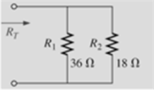
Chapter 6, Problem 4P
Find the total resistance for each configuration in Fig. 6.6. Note that only standard value resistors were used.
Expert Solution & Answer

Trending nowThis is a popular solution!

Learn your wayIncludes step-by-step video

schedule03:16
Students have asked these similar questions
Please help me with this, attached herewith is the formula how to compute the range of expected resistance values for a known marked value. Give atleast 3 resistors
The e.m.f. of a cell is balanced by the
length of 1.812 m of potentiometer wire, in the
potentiometer experiment. When a resistor of
5 ohms is connected across the cell, the
balancing length is found to be 1.51 m. Find
the internal resistance of the cell.
1.lf you compare the ohmmeter readings with the colors reading for
the given resistance. could you obtained the required tolerance for
all the resistances under test
2.State briefly the steps for measuring the unknown values of voltage
and current by the avommeter.
3.Show theoretically that then resultant of equal values of resistances
connected in parallel is equal to 1/n of any value of resistance.
Chapter 6 Solutions
Introductory Circuit Analysis (13th Edition)
Ch. 6 - For each configuration in Fig. 6.64, find the...Ch. 6 - For each configuration of Fig. 6.65, �nd the...Ch. 6 - For the network in Fig. 6.66: Find the elements...Ch. 6 - Find the total resistance for each configuration...Ch. 6 - Find the total resistance for each configuration...Ch. 6 - For each circuit board in Fig. 6.69, �nd the...Ch. 6 - The total resistance of each of the configurations...Ch. 6 - The total resistance for each configuration of...Ch. 6 - For the parallel network in Fig. 6.72, composed of...Ch. 6 - What is the ohmmeter reading for each...
Ch. 6 - Determine R1 for the network in Fig. 6.749.Ch. 6 - For the parallel network in Fig. 6.75: Find the...Ch. 6 - For the network of Fig. 6.76: Find the current...Ch. 6 - Repeat the analysis of Problem 13 for the network...Ch. 6 - For the parallel network in Fig. 6.78: Without...Ch. 6 - Given the information provided in Fig. 6.79, find:...Ch. 6 - Use the information in Fig. 6.80, to calculate:...Ch. 6 - Given the information provided in Fig. 6.81, find...Ch. 6 - For the network of Fig. 6.82, find: The voltage V....Ch. 6 - Using the information provided in Fig. 6.83 find:...Ch. 6 - For the network in Fig. 6.77: Redraw the network...Ch. 6 - For the configuration in Fig. 6.84: Find the total...Ch. 6 - Eight holiday lights are connected in parallel as...Ch. 6 - Determine the power delivered by the dc battery in...Ch. 6 - A portion of a residential service to a home is...Ch. 6 - For the network in Fig. 6.88: Find the current l1....Ch. 6 - Using Kirchhoffs current law, determine the...Ch. 6 - Using Kirchoffs current law, find the unknown...Ch. 6 - Using Kirchhoffs current law, determine the...Ch. 6 - Using the information provided in Fig. 6.92, find...Ch. 6 - Find the unknown quantities for the networks in...Ch. 6 - Find the unknown quantities for the networks of...Ch. 6 - Based solely on the resistor values, determine all...Ch. 6 - Determine one of the unknown currents of Fig....Ch. 6 - For each network of Fig. 6.97, determine the...Ch. 6 - Parts (a) through (e) of this problem should be...Ch. 6 - Find the unknown quantities for the networks in...Ch. 6 - Find resistance R for the network in Fig. 6.100...Ch. 6 - Design the network in Fig. 6.101 such that I2=2I1...Ch. 6 - Assuming identical supplies in Fig. 6.102: Find...Ch. 6 - Assuming identical supplies, determine currents...Ch. 6 - Assuming identical supplies, determine the current...Ch. 6 - For the simple series con�guration in Fig....Ch. 6 - Given the configuration in Fig. 6.106: What is the...Ch. 6 - Based on the measurements of Fig. 6.107, determine...Ch. 6 - Referring to Fig. 6.108, find the voltage Vab...Ch. 6 - The voltage Va for the network in Fig. 6.109, is...Ch. 6 - Prob. 48PCh. 6 - Using PSpice or Multisim, determine the solution...Ch. 6 - Using PSpice or Multisim, determine the solution...
Additional Engineering Textbook Solutions
Find more solutions based on key concepts
Find the values of the other currents in Figure P1.38 if ia=2A , ib=3A , id=5A , and ih=4A Figure P1.38
Electrical Engineering: Principles & Applications (7th Edition)
The switch in the bottom loop of Fig. P6.1 is closed at t = 0 and then opened at a later time t1. What is the d...
Fundamentals of Applied Electromagnetics (7th Edition)
A file that contains a Flash animation uses the __________ file extension. a. .class b. .swf c. .mp3 d. .flash
Web Development and Design Foundations with HTML5 (8th Edition)
What is an is a relationship?
Starting Out with C++ from Control Structures to Objects (8th Edition)
Explain the different aspects of the cost of a programming language.
Concepts of Programming Languages (11th Edition)
Markup Write a program that asks the user to enter an items wholesale cost and its markup percentage. It should...
Starting Out with C++: Early Objects (9th Edition)
Knowledge Booster


Learn more about
Need a deep-dive on the concept behind this application? Look no further. Learn more about this topic, electrical-engineering and related others by exploring similar questions and additional content below.Similar questions
- A PMMC instrument has internal resistance of 0.77 ko and gives full scale deflection for 35 mA. The required resistance value of multiplier resistors for employing the meter as a multi range voltmeter for voltage range 79 V will be ohms. 102562.40 O 224.94 1487.14 O -326.96arrow_forward5. A PMMC instrument gives 25mA at full scale reading when a potential difference across its terminals is 75mV. Show that how it can be used (a) as an ammeter for the current measurement in the range of 0-100A (b) as a 0 - 750V range voltmeter for the voltage measurement. Also, find the multiplying factor of shunt and voltage amplification.arrow_forwardWhich of the following is an accurate statement? A Any principal node can be used as reference node. B The potential between two principal nodes is zero. C) The principal node is considered as lower potential with respect to reference node. D There could be only one reference node in a given network.arrow_forward
- Problem No.2 group Six group of batteries are in parallel. Each has 10 cells connected in series, each has an internal emf of GV and resistance fo 0.412. a. Determine the equivalent emf and the internal resistance of the battery system.. b. If a 1-kn load resistor is connected to the battery system, what is the power dissipated to this load venistor? c. In & hre operation, determine the total energy delivered source to the 1-ks load resistor. the byarrow_forwardA 9-Vdc battery is used in series with a 1-kQ, 100-µA to create a single range ohmmeter. Find the following: a. The series resistance b. The ohmmeter reading at half scalearrow_forward2. You are employed in a large industrial plant. A 480-V, 5000-W heater is used to melt lead in a large tank. It has been decided that the heater is not sufficient to raise the temperature of the lead to the desired level. A second 5000-W heater is to be installed on the same circuit. What will be the circuit current after installation of the second heater, and what is the minimum size circuit breaker that can be used if this is a continuous-duty circuit?arrow_forward
- Solve the following problems If a 100-V resistor is connected across the terminals of a 12-V battery, how much is the current, I ? How much is the current, I, in a 470-kſ2 resistor if its voltage is 23.5 V? How much voltage will be dropped across a 40-kN resistance whose current is 250 A?arrow_forward2. Find the value of shunt resistor Rsh, that should be connected in parallel to meter to measure a 2 mA, 20 mA, 200 mA, 2 A current. The full scale current Im of the meter is 2 mA and has a resistance Rm of 1500 Q. Draw the resistance connection of the meter with proper valuesarrow_forward1.If you compare the ohmmeter readings with the colors reading for the given resistance. could you obtained the required tolerance for all the resistances under test 2.State briefly the steps for measuring the unknown values of voltage and current by the avommeter. 3.Show theoretically that then resultant of equal values of resistances connected in parallel is equal to 1/n of any value of resistance. 4.From the 4&5 steps, find the total resistance from readings of voltage and currentarrow_forward
- 3. Find the equivalent resistance seen between the indicated nodes, in terms of R. The resistors that are in parallel let them be indicated as ()//() without making the complete calculation. a) Between nodes A and B. b) Between nodes F and G. c) Between nodes B AND E. d) Between nodes D AND F.arrow_forward4. Differentiate between the accuracy of the Wheatstone bridge and Kelvin Double bridge for the respective resistance measurement. 5. Signify the bridge to be used for the measurement of a test resistor having a value around 50 kQ? 6. In contrast, the unbalanced Wheatstone bridge is often used for measurement of different physical quantities. 6.1 Determine the condition(s) for unbalanced Wheatstone bridge 6.2 State and briefly explain what are physical quantities can be measured using an unbalanced Wheatstone bridge.arrow_forward1. Obtain Vout based on the values of the resistances and I.arrow_forward
arrow_back_ios
SEE MORE QUESTIONS
arrow_forward_ios
Recommended textbooks for you
 Introductory Circuit Analysis (13th Edition)Electrical EngineeringISBN:9780133923605Author:Robert L. BoylestadPublisher:PEARSON
 Delmar's Standard Textbook Of ElectricityElectrical EngineeringISBN:9781337900348Author:Stephen L. HermanPublisher:Cengage Learning
 Programmable Logic ControllersElectrical EngineeringISBN:9780073373843Author:Frank D. PetruzellaPublisher:McGraw-Hill Education
 Fundamentals of Electric CircuitsElectrical EngineeringISBN:9780078028229Author:Charles K Alexander, Matthew SadikuPublisher:McGraw-Hill Education
 Electric Circuits. (11th Edition)Electrical EngineeringISBN:9780134746968Author:James W. Nilsson, Susan RiedelPublisher:PEARSON
 Engineering ElectromagneticsElectrical EngineeringISBN:9780078028151Author:Hayt, William H. (william Hart), Jr, BUCK, John A.Publisher:Mcgraw-hill Education,
Introductory Circuit Analysis (13th Edition)
Electrical Engineering
ISBN:9780133923605
Author:Robert L. Boylestad
Publisher:PEARSON
Delmar's Standard Textbook Of Electricity
Electrical Engineering
ISBN:9781337900348
Author:Stephen L. Herman
Publisher:Cengage Learning
Programmable Logic Controllers
Electrical Engineering
ISBN:9780073373843
Author:Frank D. Petruzella
Publisher:McGraw-Hill Education
Fundamentals of Electric Circuits
Electrical Engineering
ISBN:9780078028229
Author:Charles K Alexander, Matthew Sadiku
Publisher:McGraw-Hill Education
Electric Circuits. (11th Edition)
Electrical Engineering
ISBN:9780134746968
Author:James W. Nilsson, Susan Riedel
Publisher:PEARSON
Engineering Electromagnetics
Electrical Engineering
ISBN:9780078028151
Author:Hayt, William H. (william Hart), Jr, BUCK, John A.
Publisher:Mcgraw-hill Education,
Kirchhoff's Rules of Electrical Circuits; Author: Flipping Physics;https://www.youtube.com/watch?v=d0O-KUKP4nM;License: Standard YouTube License, CC-BY