
Introductory Circuit Analysis (13th Edition)
13th Edition
ISBN: 9780133923605
Author: Robert L. Boylestad
Publisher: PEARSON
expand_more
expand_more
format_list_bulleted
Concept explainers
Videos
Textbook Question
Chapter 6, Problem 35P
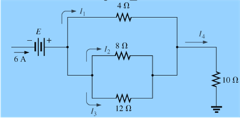
For each network of Fig. 6.97, determine the unknown currents.
Expert Solution & Answer
Want to see the full answer?
Check out a sample textbook solution
Students have asked these similar questions
EXAMPLE: Using nodal analysis, determine the potential across the 4-2
resistor and it's current.
50.
50
2 0 .
2 2
2 2
3 A
Explain the importance and use of the voltage and current divider...
Explained and discuss the observation in voltage and current divider...Atleast 300-400 words... Thank you for your help... Your help and effor is greatly appreciated Thank you so much...
b)
Describe component X
6.0V
heator
i.
The heater is designed to work from a 3.6 V supply. It has a power rating of 4.5 W at this
voltage.
By considering the current in the heater, calculate the resistance of component X when there
is the correct potential difference across the heater.
Chapter 6 Solutions
Introductory Circuit Analysis (13th Edition)
Ch. 6 - For each configuration in Fig. 6.64, find the...Ch. 6 - For each configuration of Fig. 6.65, �nd the...Ch. 6 - For the network in Fig. 6.66: Find the elements...Ch. 6 - Find the total resistance for each configuration...Ch. 6 - Find the total resistance for each configuration...Ch. 6 - For each circuit board in Fig. 6.69, �nd the...Ch. 6 - The total resistance of each of the configurations...Ch. 6 - The total resistance for each configuration of...Ch. 6 - For the parallel network in Fig. 6.72, composed of...Ch. 6 - What is the ohmmeter reading for each...
Ch. 6 - Determine R1 for the network in Fig. 6.749.Ch. 6 - For the parallel network in Fig. 6.75: Find the...Ch. 6 - For the network of Fig. 6.76: Find the current...Ch. 6 - Repeat the analysis of Problem 13 for the network...Ch. 6 - For the parallel network in Fig. 6.78: Without...Ch. 6 - Given the information provided in Fig. 6.79, find:...Ch. 6 - Use the information in Fig. 6.80, to calculate:...Ch. 6 - Given the information provided in Fig. 6.81, find...Ch. 6 - For the network of Fig. 6.82, find: The voltage V....Ch. 6 - Using the information provided in Fig. 6.83 find:...Ch. 6 - For the network in Fig. 6.77: Redraw the network...Ch. 6 - For the configuration in Fig. 6.84: Find the total...Ch. 6 - Eight holiday lights are connected in parallel as...Ch. 6 - Determine the power delivered by the dc battery in...Ch. 6 - A portion of a residential service to a home is...Ch. 6 - For the network in Fig. 6.88: Find the current l1....Ch. 6 - Using Kirchhoffs current law, determine the...Ch. 6 - Using Kirchoffs current law, find the unknown...Ch. 6 - Using Kirchhoffs current law, determine the...Ch. 6 - Using the information provided in Fig. 6.92, find...Ch. 6 - Find the unknown quantities for the networks in...Ch. 6 - Find the unknown quantities for the networks of...Ch. 6 - Based solely on the resistor values, determine all...Ch. 6 - Determine one of the unknown currents of Fig....Ch. 6 - For each network of Fig. 6.97, determine the...Ch. 6 - Parts (a) through (e) of this problem should be...Ch. 6 - Find the unknown quantities for the networks in...Ch. 6 - Find resistance R for the network in Fig. 6.100...Ch. 6 - Design the network in Fig. 6.101 such that I2=2I1...Ch. 6 - Assuming identical supplies in Fig. 6.102: Find...Ch. 6 - Assuming identical supplies, determine currents...Ch. 6 - Assuming identical supplies, determine the current...Ch. 6 - For the simple series con�guration in Fig....Ch. 6 - Given the configuration in Fig. 6.106: What is the...Ch. 6 - Based on the measurements of Fig. 6.107, determine...Ch. 6 - Referring to Fig. 6.108, find the voltage Vab...Ch. 6 - The voltage Va for the network in Fig. 6.109, is...Ch. 6 - Prob. 48PCh. 6 - Using PSpice or Multisim, determine the solution...Ch. 6 - Using PSpice or Multisim, determine the solution...
Additional Engineering Textbook Solutions
Find more solutions based on key concepts
Explain the main function of each of the following major components of a PLC: a. Processor module (CPU) b. I/O ...
Programmable Logic Controllers
Electric power systems provide energy in a variety of commercial and industrial settings. Make a list of system...
Principles and Applications of Electrical Engineering
A constant voltage of 10V is applied to a 50H inductance, as shown in Figure P3.51 Figure P3 51 The current in ...
Electrical Engineering: Principles & Applications (7th Edition)
How many coulombs do 93.8 1016 electrons represent?
Principles Of Electric Circuits
Find I0 and I1 in the circuit in Fig.P2.12.
Basic Engineering Circuit Analysis
Identify the type of input and output configuration for each diff-amp in Figure 18-35.
Electronics Fundamentals: Circuits, Devices & Applications
Knowledge Booster


Learn more about
Need a deep-dive on the concept behind this application? Look no further. Learn more about this topic, electrical-engineering and related others by exploring similar questions and additional content below.Similar questions
- Ql: find the value of different voltages that can be obtained from a 12-V battery (Van. Vnc. Ven VAc.VAD) with the help of voltage divider circuit shown belowarrow_forwardProvde a 5 capstone project that can be done by electrical engineering student. Thank you.arrow_forward5.) When a resistance of 3 ohms is placed across the terminals of battery, the current is 2A. When the resistance is increased to 42 ohms, the current falls to 1 A. Find emf of battery and its internal resistance.arrow_forward
- In an R-L parallel circuit, ET=240 volts, R=560, and XL=330. Find apparent power.arrow_forward1. Assemble the circuit as shown in diagram figure 6.4. 2. Use any value of resistor and assign it as R1, R2, R3, R4, R5. 3. Set the input voltage to 20Volts. 4. Measure the voltage reading across each resistors and record to Table 6.1. 5. Using the ammeter measure the current of each resistor and record it to Table 6.2. R, R. A, A V4 As Ra V3 Rs A2 As V2 Vs Figure 6.4 Schematic Diagram 6. Complete the data in Table 6.3 (measured value) by computing for the calculated values using the following formulas. R1 = V1/I1 R3 = V3/I3 R5 = V5/I5 VT = supply voltage E I at C = I1 – I4 – I3 E V at loop ACDBA E V at loop ĈEFDC E V at loop ACEFDBA R2 R4 RT V2/I2 V4/I4 VT/I1 %3D :VT - V1 – V3 - V2 V3 - V4 - Vs VT - Vị - V4 - V5 - V2arrow_forward6. a. The potential difference across the terminals of a battery is 8.5 V when there is a current of 3000 mA in the battery from negative to positive terminal. When the current is 2000 mA in the reverse direction, the potential difference becomes 11 V. What is the internal resistance of the battery? What is the emf of the battery?arrow_forward
arrow_back_ios
SEE MORE QUESTIONS
arrow_forward_ios
Recommended textbooks for you
 Delmar's Standard Textbook Of ElectricityElectrical EngineeringISBN:9781337900348Author:Stephen L. HermanPublisher:Cengage Learning
Delmar's Standard Textbook Of Electricity
Electrical Engineering
ISBN:9781337900348
Author:Stephen L. Herman
Publisher:Cengage Learning
Kirchhoff's Rules of Electrical Circuits; Author: Flipping Physics;https://www.youtube.com/watch?v=d0O-KUKP4nM;License: Standard YouTube License, CC-BY