
Introductory Circuit Analysis (13th Edition)
13th Edition
ISBN: 9780133923605
Author: Robert L. Boylestad
Publisher: PEARSON
expand_more
expand_more
format_list_bulleted
Concept explainers
Videos
Textbook Question
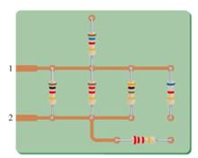
Chapter 6, Problem 6P
For each circuit board in Fig. 6.69, �nd the total resistance between connection tabs 1 and 2.
Expert Solution & Answer
Want to see the full answer?
Check out a sample textbook solution
Students have asked these similar questions
Which of the following is/are an accurate statement/s?
A The potential in any closed loop is zero.
B In parallel connection of two resistors, the current is higher for lower resistance.
The voltage divider is used to find the potential across the resistors in parallel.
The sum of current entering the junction is equal to the sum of potential in any closed loop.
INSTRUCTIONS: Solve the following problems. Show and COMPLETE solutions. Draw all CIRCUIT DIAGRAMS or the equivalent circuit (dummy circuit) as the case may be. Write your solutions on sheet/s of short bond paper.
A battery is to consist of 20 identical cells. The emf of each cell is 1.5 V and the internal resistance is 0.20 ohm. This battery will be used to supply power to a 10 ohm lamp. Determine the current on the lamp if:1. The 20 cells are connected in series 2. The 20 cells are connected in parallel 3. The 20 cells are arranged 5 cells in series in 4 parallel rows.
To measure the change in resistance of the gage(s) and indicate the location of the gauge on the beam, construct the Wheatstone bridge circuit. Calculate the Wheatstone bridge output if the gauge indicates a strain of 4000.then,Evaluate how can the number of strain gauges affects your measurement result. Justify your response with a calculation and a diagram showing the gage's placement on the beam.
Chapter 6 Solutions
Introductory Circuit Analysis (13th Edition)
Ch. 6 - For each configuration in Fig. 6.64, find the...Ch. 6 - For each configuration of Fig. 6.65, �nd the...Ch. 6 - For the network in Fig. 6.66: Find the elements...Ch. 6 - Find the total resistance for each configuration...Ch. 6 - Find the total resistance for each configuration...Ch. 6 - For each circuit board in Fig. 6.69, �nd the...Ch. 6 - The total resistance of each of the configurations...Ch. 6 - The total resistance for each configuration of...Ch. 6 - For the parallel network in Fig. 6.72, composed of...Ch. 6 - What is the ohmmeter reading for each...
Ch. 6 - Determine R1 for the network in Fig. 6.749.Ch. 6 - For the parallel network in Fig. 6.75: Find the...Ch. 6 - For the network of Fig. 6.76: Find the current...Ch. 6 - Repeat the analysis of Problem 13 for the network...Ch. 6 - For the parallel network in Fig. 6.78: Without...Ch. 6 - Given the information provided in Fig. 6.79, find:...Ch. 6 - Use the information in Fig. 6.80, to calculate:...Ch. 6 - Given the information provided in Fig. 6.81, find...Ch. 6 - For the network of Fig. 6.82, find: The voltage V....Ch. 6 - Using the information provided in Fig. 6.83 find:...Ch. 6 - For the network in Fig. 6.77: Redraw the network...Ch. 6 - For the configuration in Fig. 6.84: Find the total...Ch. 6 - Eight holiday lights are connected in parallel as...Ch. 6 - Determine the power delivered by the dc battery in...Ch. 6 - A portion of a residential service to a home is...Ch. 6 - For the network in Fig. 6.88: Find the current l1....Ch. 6 - Using Kirchhoffs current law, determine the...Ch. 6 - Using Kirchoffs current law, find the unknown...Ch. 6 - Using Kirchhoffs current law, determine the...Ch. 6 - Using the information provided in Fig. 6.92, find...Ch. 6 - Find the unknown quantities for the networks in...Ch. 6 - Find the unknown quantities for the networks of...Ch. 6 - Based solely on the resistor values, determine all...Ch. 6 - Determine one of the unknown currents of Fig....Ch. 6 - For each network of Fig. 6.97, determine the...Ch. 6 - Parts (a) through (e) of this problem should be...Ch. 6 - Find the unknown quantities for the networks in...Ch. 6 - Find resistance R for the network in Fig. 6.100...Ch. 6 - Design the network in Fig. 6.101 such that I2=2I1...Ch. 6 - Assuming identical supplies in Fig. 6.102: Find...Ch. 6 - Assuming identical supplies, determine currents...Ch. 6 - Assuming identical supplies, determine the current...Ch. 6 - For the simple series con�guration in Fig....Ch. 6 - Given the configuration in Fig. 6.106: What is the...Ch. 6 - Based on the measurements of Fig. 6.107, determine...Ch. 6 - Referring to Fig. 6.108, find the voltage Vab...Ch. 6 - The voltage Va for the network in Fig. 6.109, is...Ch. 6 - Prob. 48PCh. 6 - Using PSpice or Multisim, determine the solution...Ch. 6 - Using PSpice or Multisim, determine the solution...
Additional Engineering Textbook Solutions
Find more solutions based on key concepts
The voltage source of the circuit shown in Fig. P1.29 is given by s(t)=25cos(4104t45)(V). Obtain an expression ...
Fundamentals of Applied Electromagnetics (7th Edition)
For the “tank” circuit in Fig. 14.79, find the resonant frequency.
Figure 14.79
For Probs. 14.39, 14.71, and 1...
Fundamentals of Electric Circuits
Assume a telephone signal travels through a cable at two-thirds the speed of light. How long does it take the s...
Electric Circuits (10th Edition)
When travelers from the USA and Canada visit Europe, they encounter a different power distribution system. Wall...
Electric machinery fundamentals
A constant voltage of 10V is applied to a 50H inductance, as shown in Figure P3.51 Figure P3 51 The current in ...
Electrical Engineering: Principles & Applications (7th Edition)
With respect to the circuit in Fig. 5.90, (a) employ Thévenin’s theorem to determine the equivalent network see...
Loose Leaf for Engineering Circuit Analysis Format: Loose-leaf
Knowledge Booster


Learn more about
Need a deep-dive on the concept behind this application? Look no further. Learn more about this topic, electrical-engineering and related others by exploring similar questions and additional content below.Similar questions
- Using the rules for parallel circuits and Ohmslaw, solve for the missing values. ETE1E2E3E4ITl1I2l33.2AI4RT3.582R116R210R3R420PTP1P2P3P4arrow_forwardcan you please explain how we do the d) sectionarrow_forwardFor the voltage-divider configuration of the figure below: Show the details of your work. Sketch the DC equivalent circuit Determine and Determine andarrow_forward
- Solve the voltage across 6.8-kohm resistor of the given circuit below. 32 V AGe 6.8 kohms 6 4 V O 35.7 V O 27.3 V O 35.3 V O 13.6 Varrow_forwardThe problem of reversibility in the series type ohmmeter is solved by Using half scale measurement Adding an R, Adding an Rsh None of the choices Using shunt type Ohmmeterarrow_forwardQ6// A resistance R is measured by the ammeter-voltmeter method. The voltmeter reading is 200 V and its internal resistance is 2K. If the ammeter reading is found to be 2A, what is the value of R ? aoarrow_forward
- Solve for the circuits unknowns in the picture belowarrow_forwardIn electrolysis, there are 2 tanks connected in series where the current that flows is 5000 A. Each tank contains 12 cells which are connected in parallel. What is the amount of current that flows from the cathode to the anode of each cell?arrow_forwardDetermine the equivalent resistance between terminals a and b. O 6.9130 Q O 7.6547 Q O 5.9253 Q O 6.7520 Q R1 ww 1 Ohm R3 3 Ohms R4 4 Ohms ww R2 ww 2 Ohms R5 ww 5 Ohmsarrow_forward
- For the voltage-divider configuration of the figure below: Sketch the DC equivalent circuit Determine IDQ and VDSQ Determine VD and VS Show the details of your work.arrow_forwardUse voltage and current divider rule to solve for voltage drop in V and current drop in mA of R4.arrow_forwardwo storage batteries A and B are connected in parallel for charging from a DC source having an open circuit voltage of 14V and an internal resistance of 0.15 ohm. The open circuit voltage of A is 11V and that of B is 11.5V. The internal resistances of A and B are 0.06 ohm and 0.05 ohm respectively. Calculate the initial charging currents.arrow_forward
arrow_back_ios
SEE MORE QUESTIONS
arrow_forward_ios
Recommended textbooks for you
 Delmar's Standard Textbook Of ElectricityElectrical EngineeringISBN:9781337900348Author:Stephen L. HermanPublisher:Cengage Learning
Delmar's Standard Textbook Of Electricity
Electrical Engineering
ISBN:9781337900348
Author:Stephen L. Herman
Publisher:Cengage Learning
Kirchhoff's Rules of Electrical Circuits; Author: Flipping Physics;https://www.youtube.com/watch?v=d0O-KUKP4nM;License: Standard YouTube License, CC-BY