
Introductory Circuit Analysis (13th Edition)
13th Edition
ISBN: 9780133923605
Author: Robert L. Boylestad
Publisher: PEARSON
expand_more
expand_more
format_list_bulleted
Concept explainers
Videos
Textbook Question
Chapter 21, Problem 22P
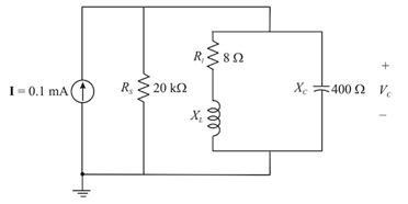
For the network in Fig. 21.63:
a. Find the value of XL for resonance.
b. Find Q1.
c. Find the resonant frequency (fp) if the bandwidth is 1 kHz.
d. Find the maximum value of the voltage Vc.
e. Sketch the curve of Vc versus frequency. Indicate its peak value, resonant frequency, and band frequencies.
Expert Solution & Answer
Want to see the full answer?
Check out a sample textbook solution
Students have asked these similar questions
7. a. The bandwidth of a series resonant circuit is 200 Hz.
If the resonant frequency is 2000 Hz, what is the
value of Q. for the circuit?
b. If R = 22, what is the value of X₂ at resonance?
c. Find the value of L and C at resonance.
d. Find the cutoff frequencies.
LAB 1
Questions
R
Vout
Vin
1. Find H(w) = Vo/Vi.
2. Derive an expression for the cutoff frequency.
3. Calculate the output voltage at frequencies: 50 Hz, 100 Hz, 150 Hz, 200 Hz,
300 Hz and 1KHZ. Assume Vin=4 v (peak-to-peak), R=1.1 k and C=1uF.
4. Calculate the cutoff frequency and the output voltage at this value.
A Parallel Resonant ckt is given in the figure. Calculate Wo, W1, W2 , QF & Bw.
Chapter 21 Solutions
Introductory Circuit Analysis (13th Edition)
Ch. 21 - Find the resonant s and fs for the series circuit...Ch. 21 - For the senes circuit in Fig. 21.51 : a. Find the...Ch. 21 - For the senes circuit in Fig. 21.52 : a. Find the...Ch. 21 - For the circuit in Fig. 21.53: a. Find the value...Ch. 21 - a. Find the bandwidth of a series resonant circuit...Ch. 21 - A series circuit has a resonant frequency of 10...Ch. 21 - a. The bandwidth of a series resonant circuit is...Ch. 21 - The cutoff frequencies of a series resonant...Ch. 21 - a. Design a series resonant circuit with an input...Ch. 21 - Design a series resonant circuit to have a...
Ch. 21 - A series resonant circuit is to resonate at s=2106...Ch. 21 - Prob. 12PCh. 21 - For the ideal parallel resonant circuit in Fig. 21...Ch. 21 - For the parallel resonant network in Fig. 21.55:...Ch. 21 - The network of Fig. 21.56 has a supply with an...Ch. 21 - For the network in Fig. 21.57: a. Find the value...Ch. 21 - The network shown in Fig. 21.58 is to resonate at...Ch. 21 - For the network in Fig. 21.59: a. Find the...Ch. 21 - Prob. 19PCh. 21 - It is desired that the impedance ZT of the high Q...Ch. 21 - For the network in Fig. 21.62: a. Find fp. b....Ch. 21 - For the network in Fig. 21.63: a. Find the value...Ch. 21 - Prob. 23PCh. 21 - For the network in Fig. 21.65: a. Find fs. fp, and...Ch. 21 - For the network in Fig. 21.66, the following are...Ch. 21 - Prob. 26PCh. 21 - For the parallel resonant circuit in Fig. 21.68:...Ch. 21 - Verify the results in Example 21.8, That is, show...Ch. 21 - Find fp and fm for the parallel resonant network...
Knowledge Booster


Learn more about
Need a deep-dive on the concept behind this application? Look no further. Learn more about this topic, electrical-engineering and related others by exploring similar questions and additional content below.Similar questions
- Calculate the gain at -3dB in dB.arrow_forward21.7 For a series RLC circuit. a) The bandwidth is 200 Hz. If the resonant frequency is 2000 Hz, what is the value of Q for the circuit? b) If R = 20, what is the value of X, at resonance? c) Find the values of L and C at resonance. d) Determine the cutoff frequencies.arrow_forwardR Vin Vout 1. Find H(w) = Vo/Vi. 2. Derive an expression for the cutoff frequency. 3. Calculate the output voltage at frequencies: 50 Hz, 100 Hz, 150 Hz, 200 Hz, 300 Hz and 1KHZ. Assume Vin=4 v (peak-to-peak), R=1.1 kN and C=1uF. 4. Calculate the cutoff frequency and the output voltage at this value.arrow_forward
- Please design the filter according to the questionarrow_forwardWhich of the following represents range of frequency measured by ADC?Select one:O'a. Peak frequency b. Threshold frequencyc. Resonance frequencyd. Bandwidtharrow_forwardCalculate the resonant frequency of the median resonator. The value of D2= 6.05 cm, D1= 1.72 cm,Lreal= 1.89 cm and the temperature is 25°. Also obtain the value in units of the frequency ofresonance.arrow_forward
- Two resistor ,5 kohms and 20 kohms are at 27 degree C. Calculate the thermal noise voltage for a 10-kHz bandwidth if they are in seriesarrow_forward1- Resonance peak in the frequency domain corresponds to : a) Resonant frequency b) Bandwidth c) Cut-off rate d) Maximum peak overshootarrow_forwardH.W: A resistor of resistance R=1000 2is maintained at 17 °C and it shunted by 100 uH inductor. Determine the ms noise voltage across the inductor over a frequency bandwi dth of: Ans: 182 x10° volt Ans: 9.22 x10 volt Ans: 2.34 x10 volt i) 15.9 kHz ii) i) 159 kHz 1590 kHzarrow_forward
- a. What is the type of oscillator? b. If Vcc = 12 V, what would be the output saturation voltage in ideal case? c. What is the resonance frequency for L1 = L2 = 50 µH and is C = 1 pF? d. What would be the value of B to satisfy Barkhausen criterion if le = 1 mA? +Vcc RFC R1 Cout Cin HE R2 RE Cearrow_forwardFind the resonant frequency for the network below. The circuit is energized by a 24-Vac,variable frequency supply. Then, for the resonant condition calculate the circuitimpedance and current.arrow_forwardFor the following given circuit; b) find Av and Avs in the medium frequency range.c) find fHi and fh0.d) draw the frequency response for the high frequency region using the bode graph and determine the cutting frequency.arrow_forward
arrow_back_ios
SEE MORE QUESTIONS
arrow_forward_ios
Recommended textbooks for you
 Introductory Circuit Analysis (13th Edition)Electrical EngineeringISBN:9780133923605Author:Robert L. BoylestadPublisher:PEARSON
 Delmar's Standard Textbook Of ElectricityElectrical EngineeringISBN:9781337900348Author:Stephen L. HermanPublisher:Cengage Learning
 Programmable Logic ControllersElectrical EngineeringISBN:9780073373843Author:Frank D. PetruzellaPublisher:McGraw-Hill Education
 Fundamentals of Electric CircuitsElectrical EngineeringISBN:9780078028229Author:Charles K Alexander, Matthew SadikuPublisher:McGraw-Hill Education
 Electric Circuits. (11th Edition)Electrical EngineeringISBN:9780134746968Author:James W. Nilsson, Susan RiedelPublisher:PEARSON
 Engineering ElectromagneticsElectrical EngineeringISBN:9780078028151Author:Hayt, William H. (william Hart), Jr, BUCK, John A.Publisher:Mcgraw-hill Education,
Introductory Circuit Analysis (13th Edition)
Electrical Engineering
ISBN:9780133923605
Author:Robert L. Boylestad
Publisher:PEARSON
Delmar's Standard Textbook Of Electricity
Electrical Engineering
ISBN:9781337900348
Author:Stephen L. Herman
Publisher:Cengage Learning
Programmable Logic Controllers
Electrical Engineering
ISBN:9780073373843
Author:Frank D. Petruzella
Publisher:McGraw-Hill Education
Fundamentals of Electric Circuits
Electrical Engineering
ISBN:9780078028229
Author:Charles K Alexander, Matthew Sadiku
Publisher:McGraw-Hill Education
Electric Circuits. (11th Edition)
Electrical Engineering
ISBN:9780134746968
Author:James W. Nilsson, Susan Riedel
Publisher:PEARSON
Engineering Electromagnetics
Electrical Engineering
ISBN:9780078028151
Author:Hayt, William H. (william Hart), Jr, BUCK, John A.
Publisher:Mcgraw-hill Education,
What is Filter & Classification of Filters | Four Types of Filters | Electronic Devices & Circuits; Author: SimplyInfo;https://www.youtube.com/watch?v=9x1Sjz-VPSg;License: Standard Youtube License