
Introductory Circuit Analysis (13th Edition)
13th Edition
ISBN: 9780133923605
Author: Robert L. Boylestad
Publisher: PEARSON
expand_more
expand_more
format_list_bulleted
Concept explainers
Videos
Textbook Question
Chapter 21, Problem 25P
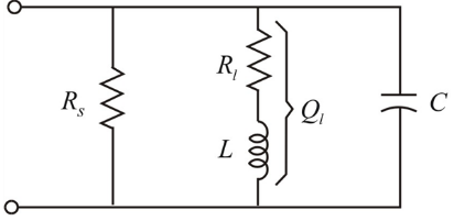
For the network in Fig. 21.66, the following are specified:
Find Rs and C.
Expert Solution & Answer
Want to see the full answer?
Check out a sample textbook solution
Students have asked these similar questions
What is the frequency and what is the period, write the formula
03: Show the signals of the outputs fin the figure below as functions of the three inputs a, b and c. Use all
eight possible combinations of a band e
abc
asnwer as soon as possible
Chapter 21 Solutions
Introductory Circuit Analysis (13th Edition)
Ch. 21 - Find the resonant s and fs for the series circuit...Ch. 21 - For the senes circuit in Fig. 21.51 : a. Find the...Ch. 21 - For the senes circuit in Fig. 21.52 : a. Find the...Ch. 21 - For the circuit in Fig. 21.53: a. Find the value...Ch. 21 - a. Find the bandwidth of a series resonant circuit...Ch. 21 - A series circuit has a resonant frequency of 10...Ch. 21 - a. The bandwidth of a series resonant circuit is...Ch. 21 - The cutoff frequencies of a series resonant...Ch. 21 - a. Design a series resonant circuit with an input...Ch. 21 - Design a series resonant circuit to have a...
Ch. 21 - A series resonant circuit is to resonate at s=2106...Ch. 21 - Prob. 12PCh. 21 - For the ideal parallel resonant circuit in Fig. 21...Ch. 21 - For the parallel resonant network in Fig. 21.55:...Ch. 21 - The network of Fig. 21.56 has a supply with an...Ch. 21 - For the network in Fig. 21.57: a. Find the value...Ch. 21 - The network shown in Fig. 21.58 is to resonate at...Ch. 21 - For the network in Fig. 21.59: a. Find the...Ch. 21 - Prob. 19PCh. 21 - It is desired that the impedance ZT of the high Q...Ch. 21 - For the network in Fig. 21.62: a. Find fp. b....Ch. 21 - For the network in Fig. 21.63: a. Find the value...Ch. 21 - Prob. 23PCh. 21 - For the network in Fig. 21.65: a. Find fs. fp, and...Ch. 21 - For the network in Fig. 21.66, the following are...Ch. 21 - Prob. 26PCh. 21 - For the parallel resonant circuit in Fig. 21.68:...Ch. 21 - Verify the results in Example 21.8, That is, show...Ch. 21 - Find fp and fm for the parallel resonant network...
Knowledge Booster


Learn more about
Need a deep-dive on the concept behind this application? Look no further. Learn more about this topic, electrical-engineering and related others by exploring similar questions and additional content below.Similar questions
- Qz Find the output respunse if the frequensyvespunse of the system is for the following 2+jw inpat: ut)arrow_forwardE. Using a suitable value for RG within the given circuit Apply a 10mVpPK 10kHz sinewave to the input.arrow_forwardVarious parameters of Schering bridge are given as follows. The voltage supply of 2 kHz is connected to terminals A and C and detector to points B and D. Arm AB comprises the unknown Resistor R1 and capacitor C1. Arm BC consists of resistor R2 of 18k 2. Arm DA consists of capacitor C2 of 0.06 µf. Arm CD has R3 of 1.5k2 and C3 of 2nf are in parallel. Calculate (i) the capacitance (C1) (ii) the equivalent series resistance (R1) and (iii) dissipation factor. Also draw the schematic diagram.arrow_forward
- For the given circuit with a 12.81 Vpeak sinusoidal input, Vin, what is the value of Vout (in V) when input is a positive half cycle?Use practical model, Silicon diode. Vin Vout Round your answer to 2 decimal places. Rarrow_forward13. CALCULATE THE OUTPUT VOLTAGE OF THE GIVEN CIRCUIT BELOW 12VRMS 50Hz F1 a) 3.86 V dc b) 5.4 V dc c) 7.632 V dc d) 10.8 V dc e) 12 V dc f) 13.32 V dc D1 D2 D3 D4 g) 16.36 V dc h) none of the above C1 1000μF Voutarrow_forwardThe buck converter with resistive load has the input voltage of 30[V], the output voltage of 10 [V] (constant), and the switching frequency of 40 [kHz]. If the output average power is 25[W], then determine the size of the inductor such that the minimum inductor current is 25% of the average inductor current. O 118.52 mikro Henry O 32.78 mikro Henry O 44.44 mikro Henry O 148.15 mikro Henry O 74.07 mikro Henry O 59.26 mikro Henry O 88.89 mikro Henry O 124.56 mikro Henryarrow_forward
- Calculate for, when B=80a) VB b) VE c) IE d) IB e) Ic f) Vc g) VCEarrow_forwardFor the fixed-bias configuration of Figure Below, determine: IBQ, ICQ, VCEQ, VCB, .and VE 16 V Ico 1.8 kQ 510 ΚΩ Vc VB VCEQ B=120 IBQ VE إضافة ملف إرسال نسخة من ردي إلي. إرسالarrow_forwardusiy the pur tial fraction Xcn) for me thed to fråd w/ forarrow_forward
- 2. Assume the VDS of M1 and M2 is negligible when they are switched on. Find the equivalent resistance from V1 to V2 if: a. C=2.2 nF and the switching frequency fc = 33.22 kHz b. C=0.22 nF and the switching frequency fc = 33.22 kHz M1 M2 OV2arrow_forward3) The op-omps in the crcuit ore idcal o Find iq=? b) Find the value of the left dource voltoge for uhich ia=0 220kn lokn 16V tia 33 ka 1ke 1SOMUarrow_forwardFor the three circuit elelents in the image find Zeqarrow_forward
arrow_back_ios
SEE MORE QUESTIONS
arrow_forward_ios
Recommended textbooks for you
 Introductory Circuit Analysis (13th Edition)Electrical EngineeringISBN:9780133923605Author:Robert L. BoylestadPublisher:PEARSON
 Delmar's Standard Textbook Of ElectricityElectrical EngineeringISBN:9781337900348Author:Stephen L. HermanPublisher:Cengage Learning
 Programmable Logic ControllersElectrical EngineeringISBN:9780073373843Author:Frank D. PetruzellaPublisher:McGraw-Hill Education
 Fundamentals of Electric CircuitsElectrical EngineeringISBN:9780078028229Author:Charles K Alexander, Matthew SadikuPublisher:McGraw-Hill Education
 Electric Circuits. (11th Edition)Electrical EngineeringISBN:9780134746968Author:James W. Nilsson, Susan RiedelPublisher:PEARSON
 Engineering ElectromagneticsElectrical EngineeringISBN:9780078028151Author:Hayt, William H. (william Hart), Jr, BUCK, John A.Publisher:Mcgraw-hill Education,
Introductory Circuit Analysis (13th Edition)
Electrical Engineering
ISBN:9780133923605
Author:Robert L. Boylestad
Publisher:PEARSON
Delmar's Standard Textbook Of Electricity
Electrical Engineering
ISBN:9781337900348
Author:Stephen L. Herman
Publisher:Cengage Learning
Programmable Logic Controllers
Electrical Engineering
ISBN:9780073373843
Author:Frank D. Petruzella
Publisher:McGraw-Hill Education
Fundamentals of Electric Circuits
Electrical Engineering
ISBN:9780078028229
Author:Charles K Alexander, Matthew Sadiku
Publisher:McGraw-Hill Education
Electric Circuits. (11th Edition)
Electrical Engineering
ISBN:9780134746968
Author:James W. Nilsson, Susan Riedel
Publisher:PEARSON
Engineering Electromagnetics
Electrical Engineering
ISBN:9780078028151
Author:Hayt, William H. (william Hart), Jr, BUCK, John A.
Publisher:Mcgraw-hill Education,
What is Filter & Classification of Filters | Four Types of Filters | Electronic Devices & Circuits; Author: SimplyInfo;https://www.youtube.com/watch?v=9x1Sjz-VPSg;License: Standard Youtube License