
Introductory Circuit Analysis (13th Edition)
13th Edition
ISBN: 9780133923605
Author: Robert L. Boylestad
Publisher: PEARSON
expand_more
expand_more
format_list_bulleted
Concept explainers
Videos
Textbook Question
Chapter 21, Problem 21P
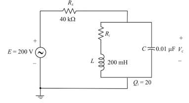
For the network in Fig. 21.62:
a. Find fp.
b. Calculate the magnitude of Vc at resonance (fp).
c. Determine the power absorbed at resonance.
d. Find the BW.
Expert Solution & Answer
Want to see the full answer?
Check out a sample textbook solution
Students have asked these similar questions
Can we obtain a plot of XL against frequency f experimentally?
Approximately, determine the Vpp and frequency of the given signal:
Reading settings: 20V/DIV and 5ms/DIV
Explain your approximation
Block Diagram:
clipper
R
Vo
V81
V82
Fig. (7) [9]
Fig. (6) [8]
Block Diagram:
clamper
Vi
10V
Fig. (9) [9]
Fig. (8) [9]
- Describe the electronic behavior for clipper and clamper
circuits.
- Draw the transfer characteristic Vo versus V.
to
Chapter 21 Solutions
Introductory Circuit Analysis (13th Edition)
Ch. 21 - Find the resonant s and fs for the series circuit...Ch. 21 - For the senes circuit in Fig. 21.51 : a. Find the...Ch. 21 - For the senes circuit in Fig. 21.52 : a. Find the...Ch. 21 - For the circuit in Fig. 21.53: a. Find the value...Ch. 21 - a. Find the bandwidth of a series resonant circuit...Ch. 21 - A series circuit has a resonant frequency of 10...Ch. 21 - a. The bandwidth of a series resonant circuit is...Ch. 21 - The cutoff frequencies of a series resonant...Ch. 21 - a. Design a series resonant circuit with an input...Ch. 21 - Design a series resonant circuit to have a...
Ch. 21 - A series resonant circuit is to resonate at s=2106...Ch. 21 - Prob. 12PCh. 21 - For the ideal parallel resonant circuit in Fig. 21...Ch. 21 - For the parallel resonant network in Fig. 21.55:...Ch. 21 - The network of Fig. 21.56 has a supply with an...Ch. 21 - For the network in Fig. 21.57: a. Find the value...Ch. 21 - The network shown in Fig. 21.58 is to resonate at...Ch. 21 - For the network in Fig. 21.59: a. Find the...Ch. 21 - Prob. 19PCh. 21 - It is desired that the impedance ZT of the high Q...Ch. 21 - For the network in Fig. 21.62: a. Find fp. b....Ch. 21 - For the network in Fig. 21.63: a. Find the value...Ch. 21 - Prob. 23PCh. 21 - For the network in Fig. 21.65: a. Find fs. fp, and...Ch. 21 - For the network in Fig. 21.66, the following are...Ch. 21 - Prob. 26PCh. 21 - For the parallel resonant circuit in Fig. 21.68:...Ch. 21 - Verify the results in Example 21.8, That is, show...Ch. 21 - Find fp and fm for the parallel resonant network...
Knowledge Booster


Learn more about
Need a deep-dive on the concept behind this application? Look no further. Learn more about this topic, electrical-engineering and related others by exploring similar questions and additional content below.Similar questions
- R Vin Vout 1. Find H(w) = Vo/Vi. 2. Derive an expression for the cutoff frequency. 3. Calculate the output voltage at frequencies: 50 Hz, 100 Hz, 150 Hz, 200 Hz, 300 Hz and 1KHZ. Assume Vin=4 v (peak-to-peak), R=1.1 kN and C=1uF. 4. Calculate the cutoff frequency and the output voltage at this value.arrow_forwardFrequency bands: What are low and medium frequency bands? What are the difference of the 2 and what are they used for?arrow_forwardWhich of the following diode is used in high frequency switching operations? O a. General purpose diode O b. Schottky diode PN junction diode O d. Şilicon junction diode Choose the % derating factor of the string which is having 9 number of SCR connected in series to withstand a DC voltage of 1733 V and steady state voltage rating of 896 V. O a. 78.51 O b. 10.75 Oc. 21.49 O d. 5.74 o searcharrow_forward
- 5. QUESTIONS (1) If the inductance in the tank circuit is 80nH and we wish to get a resonance frequency of 100MHZ, what capacitance value of varactor diode should be?arrow_forwarda) Write the equation of the modulated wave. b) Sketch the waveform of modulated wave and write its equation if the modulation type is AM/DSB- SC. 62 -8 -14arrow_forwardLAB 1 Questions R Vout Vin 1. Find H(w) = Vo/Vi. 2. Derive an expression for the cutoff frequency. 3. Calculate the output voltage at frequencies: 50 Hz, 100 Hz, 150 Hz, 200 Hz, 300 Hz and 1KHZ. Assume Vin=4 v (peak-to-peak), R=1.1 k and C=1uF. 4. Calculate the cutoff frequency and the output voltage at this value.arrow_forward
- In a certain UJT, RB1 = 2.5 kohms and RB2 = 4 kohms. What is the intrinsic standoff ratio? A. 0.8453 B. 0.3846 (c) C. 0.7232 D. 0.6154arrow_forwardDesign (only the block diagram) an Armstrong indirectly FM modulator to generate an FM carrier with a carrier frequency of 98.1MHz and df (frequency deviation) =75kHz.A narrowband FM generator is available at a carrier frequency of 100 KHz and a (frequency deviation) df=10Hz.The stockroom has an oscillator with an adjustable frequency in the range of 10 to 11MHz.There are plenty of Frequency multipliers.arrow_forward21.5 For a series BLC circuit. a) Find the bandwidth of a series resonant circuit having resonant frequency of 6000 Hz and a Q of 15. b) Find the cutoff frequencies. c) If the resistance of the circuit at resonance 32, what are the values of X, and Xc in ohms? d) What is the power dissipated at the half-power frequencies if the maximum current flowing through the circuit is 0.5 Amps?arrow_forward
- If a modulating signal of 20Khz is applied to an AM modulator of the S.S.B type, the bandwidth will be of value:arrow_forward21.5 For a series RLC circuit. a) Find the bandwidth of a series resonant circuit having a resonant frequency of 6000 Hz and a Q of 15. b) Find the cutoff frequencies. c) If the resistance of the circuit at resonance 32, what are the values of X, and Xc in ohms? d) What is the power dissipated at the half-power frequencies if the maximum current flowing through the circuit is 0.5 Amps?arrow_forwardShow the Common Emitter amplified output when sinusoidal 100Hz signal is applied at the input capacitor. Plz show the circuit diagramarrow_forward
arrow_back_ios
SEE MORE QUESTIONS
arrow_forward_ios
Recommended textbooks for you
 Introductory Circuit Analysis (13th Edition)Electrical EngineeringISBN:9780133923605Author:Robert L. BoylestadPublisher:PEARSON
 Delmar's Standard Textbook Of ElectricityElectrical EngineeringISBN:9781337900348Author:Stephen L. HermanPublisher:Cengage Learning
 Programmable Logic ControllersElectrical EngineeringISBN:9780073373843Author:Frank D. PetruzellaPublisher:McGraw-Hill Education
 Fundamentals of Electric CircuitsElectrical EngineeringISBN:9780078028229Author:Charles K Alexander, Matthew SadikuPublisher:McGraw-Hill Education
 Electric Circuits. (11th Edition)Electrical EngineeringISBN:9780134746968Author:James W. Nilsson, Susan RiedelPublisher:PEARSON
 Engineering ElectromagneticsElectrical EngineeringISBN:9780078028151Author:Hayt, William H. (william Hart), Jr, BUCK, John A.Publisher:Mcgraw-hill Education,
Introductory Circuit Analysis (13th Edition)
Electrical Engineering
ISBN:9780133923605
Author:Robert L. Boylestad
Publisher:PEARSON
Delmar's Standard Textbook Of Electricity
Electrical Engineering
ISBN:9781337900348
Author:Stephen L. Herman
Publisher:Cengage Learning
Programmable Logic Controllers
Electrical Engineering
ISBN:9780073373843
Author:Frank D. Petruzella
Publisher:McGraw-Hill Education
Fundamentals of Electric Circuits
Electrical Engineering
ISBN:9780078028229
Author:Charles K Alexander, Matthew Sadiku
Publisher:McGraw-Hill Education
Electric Circuits. (11th Edition)
Electrical Engineering
ISBN:9780134746968
Author:James W. Nilsson, Susan Riedel
Publisher:PEARSON
Engineering Electromagnetics
Electrical Engineering
ISBN:9780078028151
Author:Hayt, William H. (william Hart), Jr, BUCK, John A.
Publisher:Mcgraw-hill Education,
What is Filter & Classification of Filters | Four Types of Filters | Electronic Devices & Circuits; Author: SimplyInfo;https://www.youtube.com/watch?v=9x1Sjz-VPSg;License: Standard Youtube License