
Concept explainers
Videos
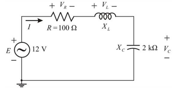
For the senes circuit in Fig. 21.52 :
a. Find the value of XL for resonance.
b. Determine the magnitude of the current I at resonance.
c. Find the voltages VR VL, and Vc at resonance, and compare their magnitudes.
d. Determine the quality factor of the circuit. Is it a high-or low-Q circuit?
e. If the resonant frequency is 5kHZ, determine the value of L and C.
f. Find the bandwidth of the response if the resonant frequency is 5 kHZ.
g. What are the low and high cutoff frequencies?
Want to see the full answer?
Check out a sample textbook solution
Chapter 21 Solutions
Introductory Circuit Analysis (13th Edition)
Additional Engineering Textbook Solutions
Thinking Like an Engineer: An Active Learning Approach (4th Edition)
Elementary Surveying: An Introduction To Geomatics (15th Edition)
Java: An Introduction to Problem Solving and Programming (8th Edition)
Java How to Program, Early Objects (11th Edition) (Deitel: How to Program)
SURVEY OF OPERATING SYSTEMS
Degarmo's Materials And Processes In Manufacturing


- I only need help with d)arrow_forwardanswer with handwritingarrow_forwardQ.5: b. Choose the suitable choice for nine of the following sentences. 1. In order to lune a parallel resonant circuit to a lower frequency. the capacitor must........ > Be decrease. a. Be increase d. Remain the same. e. Be Zero. 2 In series as well as parallel resonance circuit, increase in resistance would cause the bandwidth is...... a. Increase in both circuits. (h. Decrease in series eircuit and increase in parallel circuit. d. lucrease in series circuit and decrease in parallel circuit. circuit. e Decrease in both circuits. 3. In a very low frequency a series resonance circuit behaves as almost purely a. Resistive. c. Inductive. d. Inductive and capacitive. b. Capacitive: 4. Real part of the total impedance at resonance for complicated AC circuit is a. Positive Value. b. Zero Value. 5. For admittance locus the maximum obtained power factor is depend on: a. Maximum current b. Maximum voltage c. Minimum power 4. Minimum angle 6. Any non-sinusoidal symmetrical waves are basically…arrow_forward
- Determine the gain, Vout/ Vin, for the given circuit. What is the resonant frequency of the circuit, in Hertz? + Vout Vinarrow_forwardb. Choose the suitable choice foL ping of the following sentences 18 Maces 1. In order to tune a parallel resonant circuit to a lewer frequency the capacitor must a. Be increase. b. Be decrease. . BeZero. Remain the same 2. Ina very low frequency a series resonance behaves as Imost purely .......... circuit a Resistive. b Capacitive. . Inductive. d. Inductive and capacitive 3. Real part of the total impedance at resonance for complicated AC circuit is a. Positive Value. b. Zero Value. Negative Value. d. Complex value 4. For admittance locus the maximum obtained power factor is depend on a Maximum current b. Maximum voltage . Minimum power d. Minimum angle 5 Any non sinusoidal symmetrical waves are basically composite from fundamental wave plas .. of harmonics waves. aodd b. even . odd even d odd of even 6. If we append an inductance in series to an RL series circuit the time constant will be a Increases b. Decreases. Increases and Decreases. Increases or Decreases 7. The double energy…arrow_forwardThe cutoff frequencies of a series resonant circuit are 5400 Hz and 6000 Hz. a) Find the bandwidth of the circuit. b) If Qs is 9.5, find the resonant frequency of the circuit. c) If the resistance of the circuit is 2 2 find the value of XL and XC at resonance. d) Find the value of L and C at resonance.arrow_forward
- do part d and earrow_forward*9. Design a series resonant circuit with an input voltage of 5 V 20° to have the following specifications: a. A peak current of 500 mA at resonance b. A bandwidth of 120 Hz c. A resonant frequency of 8400 Hz Find the value of L and C and the cutoff frequencies.arrow_forward3. Bode magnitude plot is drawn between a) magnitude of network function and w b) dB magnitude and log w c) dB magnitude and w d) loge (magnitude) and log warrow_forward
- Q.17: For the circuit shown if RL varies from 5 to 102: 1. Did the value of "R" effect on resonance, prove it using the locus diagram 2. Prove that there is no resonance case in the circuit. 3. Find the new value of "Rc" that makes the circuit at resonance. (Ans.: Rc=4.9Q, & 8Q) Rc RL VT Xc -j42 XL wwHarrow_forwardCalculate the resonant frequency of the median resonator. The value of D2= 6.05 cm, D1= 1.72 cm,Lreal= 1.89 cm and the temperature is 25°. Also obtain the value in units of the frequency ofresonance.arrow_forward21.3 For the series circuit in Fig. 21.52: a) Find the value of X. for resonance. R = 100 A b) Determine the magnitude of the current I at resonance. 12 V 2 k V c) Find the voltages YR, Y, and ye at resonance, and compare their magnitudes. d) Determine the quality factor of the circuit. Is it a high- or low-Q circuit? e) If the resonant frequency is 5 kHz, determine the value of L and C. f) Find the bandwidth of the response if the resonant frequency is 5 kHz. g) What are the low and high cutoff frequencies?arrow_forward
 Introductory Circuit Analysis (13th Edition)Electrical EngineeringISBN:9780133923605Author:Robert L. BoylestadPublisher:PEARSON
 Delmar's Standard Textbook Of ElectricityElectrical EngineeringISBN:9781337900348Author:Stephen L. HermanPublisher:Cengage Learning
 Programmable Logic ControllersElectrical EngineeringISBN:9780073373843Author:Frank D. PetruzellaPublisher:McGraw-Hill Education
 Fundamentals of Electric CircuitsElectrical EngineeringISBN:9780078028229Author:Charles K Alexander, Matthew SadikuPublisher:McGraw-Hill Education
 Electric Circuits. (11th Edition)Electrical EngineeringISBN:9780134746968Author:James W. Nilsson, Susan RiedelPublisher:PEARSON
 Engineering ElectromagneticsElectrical EngineeringISBN:9780078028151Author:Hayt, William H. (william Hart), Jr, BUCK, John A.Publisher:Mcgraw-hill Education,