
Introductory Circuit Analysis (13th Edition)
13th Edition
ISBN: 9780133923605
Author: Robert L. Boylestad
Publisher: PEARSON
expand_more
expand_more
format_list_bulleted
Concept explainers
Videos
Textbook Question
Chapter 21, Problem 20P
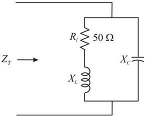
It is desired that the impedance ZT of the high Q circuit in Fig. 21.61 be 50 k
a. Find the value of XL.
b. Compute Xc.
c. Find the resonant frequency
d. Find the value of C.
Expert Solution & Answer
Want to see the full answer?
Check out a sample textbook solution
Students have asked these similar questions
7. a. The bandwidth of a series resonant circuit is 200 Hz.
If the resonant frequency is 2000 Hz, what is the
value of Q. for the circuit?
b. If R = 22, what is the value of X₂ at resonance?
c. Find the value of L and C at resonance.
d. Find the cutoff frequencies.
Question 02:
A) How do you use Kirchhoff's law? What are the limitations of Kirchhoff's law?
B) What is resonance in RLC circuit? Define the Q-factor in RLC series circuit.
b. Choose the suitable choice foL ping of
the following sentences 18 Maces 1. In
order to tune a parallel resonant circuit to a
lewer frequency the capacitor must a. Be
increase. b. Be decrease. . BeZero. Remain
the same 2. Ina very low frequency a series
resonance behaves as Imost purely ..........
circuit a Resistive. b Capacitive. . Inductive.
d. Inductive and capacitive 3. Real part of the
total impedance at resonance for complicated
AC circuit is
a. Positive Value. b. Zero
Value. Negative Value. d. Complex value 4.
For admittance locus the maximum obtained
power factor is depend on a Maximum current
b. Maximum voltage . Minimum power d.
Minimum angle 5 Any non sinusoidal
symmetrical waves are basically composite
from fundamental wave plas .. of harmonics
waves. aodd b. even . odd even d odd of
even 6. If we append an inductance in series
to an RL series circuit the time constant will
be a Increases b. Decreases. Increases and
Decreases. Increases or Decreases 7. The
double energy…
Chapter 21 Solutions
Introductory Circuit Analysis (13th Edition)
Ch. 21 - Find the resonant s and fs for the series circuit...Ch. 21 - For the senes circuit in Fig. 21.51 : a. Find the...Ch. 21 - For the senes circuit in Fig. 21.52 : a. Find the...Ch. 21 - For the circuit in Fig. 21.53: a. Find the value...Ch. 21 - a. Find the bandwidth of a series resonant circuit...Ch. 21 - A series circuit has a resonant frequency of 10...Ch. 21 - a. The bandwidth of a series resonant circuit is...Ch. 21 - The cutoff frequencies of a series resonant...Ch. 21 - a. Design a series resonant circuit with an input...Ch. 21 - Design a series resonant circuit to have a...
Ch. 21 - A series resonant circuit is to resonate at s=2106...Ch. 21 - Prob. 12PCh. 21 - For the ideal parallel resonant circuit in Fig. 21...Ch. 21 - For the parallel resonant network in Fig. 21.55:...Ch. 21 - The network of Fig. 21.56 has a supply with an...Ch. 21 - For the network in Fig. 21.57: a. Find the value...Ch. 21 - The network shown in Fig. 21.58 is to resonate at...Ch. 21 - For the network in Fig. 21.59: a. Find the...Ch. 21 - Prob. 19PCh. 21 - It is desired that the impedance ZT of the high Q...Ch. 21 - For the network in Fig. 21.62: a. Find fp. b....Ch. 21 - For the network in Fig. 21.63: a. Find the value...Ch. 21 - Prob. 23PCh. 21 - For the network in Fig. 21.65: a. Find fs. fp, and...Ch. 21 - For the network in Fig. 21.66, the following are...Ch. 21 - Prob. 26PCh. 21 - For the parallel resonant circuit in Fig. 21.68:...Ch. 21 - Verify the results in Example 21.8, That is, show...Ch. 21 - Find fp and fm for the parallel resonant network...
Knowledge Booster


Learn more about
Need a deep-dive on the concept behind this application? Look no further. Learn more about this topic, electrical-engineering and related others by exploring similar questions and additional content below.Similar questions
- Determine the gain, Vout/ Vin, for the given circuit. What is the resonant frequency of the circuit, in Hertz? + Vout Vinarrow_forward9) Amoving coil voltmeter has a uniform scale with 100 divisions, the full scalereading is 200 Vand 1/10 of a scale division can be estimated with a fair degree of certainty. Determine the resolution of the instrument in volt. 10) Eight different students tuned in the circuit for resonance and the values ofresonant frequency in kHz were recorded as: 412, 428, 423, 415, 426, 411, 423, 416 Calculate the following: (a) Arithmetic mean (b) Average deviation (c) Standard deviation (d) Variance.arrow_forward21.7 For a series RLC circuit. a) The bandwidth is 200 Hz. If the resonant frequency is 2000 Hz, what is the value of Q for the circuit? b) If R = 22, what is the value of XL at resonance? c) Find the values of L and C at resonance. d) Determine the cutoff frequencies. |arrow_forward
- 4. The Bode plot shown below represents the voltage gain of a particular amplifier. Sketch the input and output waveforms, v,() and v(1) if the input to the amplifier is v, (1) = 10 + 10cos(400t + 60°) mV. Use the graph paper on the next page for your sketches and label the minimum and maximum value for each waveform. 60 Bode Diagram 58 56 54 52 50 48 46 44 42 40 -5 -10 -15 -20 -25 -30 -35 -40 -45 -50 -55 -60 100 101 102 Frequency (rad/s) 10 104 105 (Bap) aseud Magnitude (dB)arrow_forwardH.W: A resistor of resistance R=1000 2is maintained at 17 °C and it shunted by 100 uH inductor. Determine the ms noise voltage across the inductor over a frequency bandwi dth of: Ans: 182 x10° volt Ans: 9.22 x10 volt Ans: 2.34 x10 volt i) 15.9 kHz ii) i) 159 kHz 1590 kHzarrow_forwardThe bandwidth of a series resonant circuit is 400 Hz. a. If the resonant frequency is 4000 Hz, what is the value of Qs? 10 , what is the value of X, at resonance? b. If R c. Find the inductance L =arrow_forward
- of it H PAGE 29 EEI-ELECTI CKTI FINALCOVERAGE TOPIC AND ASSIGNMENT SERIES RESONANCE (R, L&C CKTS) WHERE: I= CURRENT IN AMPS V:IMPRESSED VOLTAGEN VOIS aL R= RESISTANCEE IN OH MS L= INDUCTANCE IN HENRY C CAPACITANCE IRLFARAD FIGURE RESONANT FREQUENCY FORMULA HZ ASSIENMENT PROBLEM: AN IMPEDANCE COIL HAVING ARESISTANCE AND INDUCTANCE OF 20 AND I.5 MILLLHENRY RESPECTIVELY CONNECTED IN SERIES WITH A CAPACITOR. CALCULATE THE VALUE OF CAPACITANCE IFTHE CKT WILL OPERATE AT RESONANCE.THE RESONANT EREQUENC(to 15 4.5 KHZ.arrow_forward2. Frequency response 2.1 A series resonant circuit has an inductor of 2 mH and a capacitor of 12 uF. The circuit has a quality factor of 4. Find the resonance, system frequency, Natural Frequency, Impedance, Bandwidth, Half-Power Frequency, and Resonance Current with a 20sinwt Voltage Source.arrow_forwardRo = 5kQ. Determine the lower cutoff frequency f (in kHz) ? +Vcc MF ZTC 5k2 2.5 mA MF -Vec Assume: be PF а. 1.2 O b. 0.20 c. 16.7 O d. 100arrow_forward
- The bandwidth of a composite signal is the difference between the highest and a. zero frequency b. lowest frequencies c. two Parallel frequencies d. None of Abovearrow_forward*9. Design a series resonant circuit with an input voltage of 5V 20° to have the following specifications: a. A peak current of 500 mA at resonance b. A bandwidth of 120 Hz c. A resonant frequency of 8400 Hz Find the value of L and C and the cutoff frequencies. *10. Design a series resonant circuit to have a bandwidth of 400 Hz using a coil with a Q, of 20 and a resistance of 2 2. Find the values of L and C and the cutoff frequen- cies.arrow_forwardDesign a series resonant circuit with an input voltage of 5 V 20° to have the following specifications: a. A peak current of 500 mA at resonance b. A bandwidth of 120 Hz c. A resonant frequency of 8400 Hz Find the value of L and C and the cutoff frequencies.arrow_forward
arrow_back_ios
SEE MORE QUESTIONS
arrow_forward_ios
Recommended textbooks for you
 Introductory Circuit Analysis (13th Edition)Electrical EngineeringISBN:9780133923605Author:Robert L. BoylestadPublisher:PEARSON
 Delmar's Standard Textbook Of ElectricityElectrical EngineeringISBN:9781337900348Author:Stephen L. HermanPublisher:Cengage Learning
 Programmable Logic ControllersElectrical EngineeringISBN:9780073373843Author:Frank D. PetruzellaPublisher:McGraw-Hill Education
 Fundamentals of Electric CircuitsElectrical EngineeringISBN:9780078028229Author:Charles K Alexander, Matthew SadikuPublisher:McGraw-Hill Education
 Electric Circuits. (11th Edition)Electrical EngineeringISBN:9780134746968Author:James W. Nilsson, Susan RiedelPublisher:PEARSON
 Engineering ElectromagneticsElectrical EngineeringISBN:9780078028151Author:Hayt, William H. (william Hart), Jr, BUCK, John A.Publisher:Mcgraw-hill Education,
Introductory Circuit Analysis (13th Edition)
Electrical Engineering
ISBN:9780133923605
Author:Robert L. Boylestad
Publisher:PEARSON
Delmar's Standard Textbook Of Electricity
Electrical Engineering
ISBN:9781337900348
Author:Stephen L. Herman
Publisher:Cengage Learning
Programmable Logic Controllers
Electrical Engineering
ISBN:9780073373843
Author:Frank D. Petruzella
Publisher:McGraw-Hill Education
Fundamentals of Electric Circuits
Electrical Engineering
ISBN:9780078028229
Author:Charles K Alexander, Matthew Sadiku
Publisher:McGraw-Hill Education
Electric Circuits. (11th Edition)
Electrical Engineering
ISBN:9780134746968
Author:James W. Nilsson, Susan Riedel
Publisher:PEARSON
Engineering Electromagnetics
Electrical Engineering
ISBN:9780078028151
Author:Hayt, William H. (william Hart), Jr, BUCK, John A.
Publisher:Mcgraw-hill Education,
What is Filter & Classification of Filters | Four Types of Filters | Electronic Devices & Circuits; Author: SimplyInfo;https://www.youtube.com/watch?v=9x1Sjz-VPSg;License: Standard Youtube License