
Videos
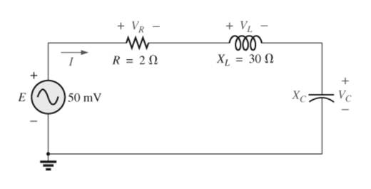
For the senes circuit in Fig. 21.51 :
a. Find the value of Xc for resonance.
b. Determine the total impedance of the circuit at resonance.
c. Find the magnitude of the current I.
d. Calculate the voltages VR VL. and Vc at resonance. How are VL and Vc related? How does VR compare to the applied voltage E?
e. What is the quality factor of the circuit? Is it a high or low Q circuit?
f. What is the power dissipated by the circuit at resonance?
Want to see the full answer?
Check out a sample textbook solution
Chapter 21 Solutions
Introductory Circuit Analysis (13th Edition)
Additional Engineering Textbook Solutions
Loose Leaf for Engineering Circuit Analysis Format: Loose-leaf
Electric machinery fundamentals
Electric Circuits. (11th Edition)
Electronics Fundamentals: Circuits, Devices & Applications
Electric Circuits (10th Edition)
Principles and Applications of Electrical Engineering


- 21.7 For a series RLC circuit. a) The bandwidth is 200 Hz. If the resonant frequency is 2000 Hz, what is the value of Q for the circuit? b) If R = 22, what is the value of XL at resonance? c) Find the values of L and C at resonance. d) Determine the cutoff frequencies. |arrow_forward7. a. The bandwidth of a series resonant circuit is 200 Hz. If the resonant frequency is 2000 Hz, what is the value of Q. for the circuit? b. If R = 22, what is the value of X₂ at resonance? c. Find the value of L and C at resonance. d. Find the cutoff frequencies.arrow_forward21.5 For a series RLC circuit. a) Find the bandwidth of a series resonant circuit having a resonant frequency of 6000 Hz and a Q of 15. b) Find the cutoff frequencies. c) If the resistance of the circuit at resonance 32, what are the values of X, and Xc in ohms? d) What is the power dissipated at the half-power frequencies if the maximum current flowing through the circuit is 0.5 Amps?arrow_forward
- Q.5: b. Choose the suitable choice for nine of the following sentences. 1. In order to lune a parallel resonant circuit to a lower frequency. the capacitor must........ > Be decrease. a. Be increase d. Remain the same. e. Be Zero. 2 In series as well as parallel resonance circuit, increase in resistance would cause the bandwidth is...... a. Increase in both circuits. (h. Decrease in series eircuit and increase in parallel circuit. d. lucrease in series circuit and decrease in parallel circuit. circuit. e Decrease in both circuits. 3. In a very low frequency a series resonance circuit behaves as almost purely a. Resistive. c. Inductive. d. Inductive and capacitive. b. Capacitive: 4. Real part of the total impedance at resonance for complicated AC circuit is a. Positive Value. b. Zero Value. 5. For admittance locus the maximum obtained power factor is depend on: a. Maximum current b. Maximum voltage c. Minimum power 4. Minimum angle 6. Any non-sinusoidal symmetrical waves are basically…arrow_forwardCan we obtain a plot of XL against frequency f experimentally?arrow_forwardPlease design the filter according to the questionarrow_forward
- An amplifier has a midband voltage gain of 120 operating between f1=10 Hz (lower cut-off) to 100 kHz (upper cut-off). What is the output voltage of the circuit at 3kHz if the input voltage is 20mVpeak-to-peak? 0.85 Vpeak O 1.2 Vrms 1.2 Vpeak O 2.4 Vpeakarrow_forwardP3 For the series RLC circuit given in Figure 4 for Vs=10sinot R=2.2 2, L=100 uH and C=1000 uF a) Obtain the resonant frequency and the half-power frequencies. b) Calculate the quality factor and bandwidth. c) Determine the amplitude of the current at 60, 6 and 02. d) Plot the current amplitude versus frequency e) Use LTSPICE to plot frequency response.arrow_forwardFor the network of figure below: a. Find Avmid = Vo / Vi. b. Determine fLs. fLc. and fLE- c. Determine the low cutoff frequency. d. Sketch the asymptotes of the Bode plot defined by the low cutoff frequency of part (c). e. Sketch the low-frequency response for the amplifier using the results of part (d) 20 V he = 140 hie = 0.86 k2 h=1.5x 10 4 hoe= 25 uS 2.2 k2 470 k2 I k2 5 μF 5 µF 1.2 k2 10 µFarrow_forward
- HIGH VOLTAGE(Can you explain in detail? Thank you) Q1 : A 100 kVA, 50 Hz, 230/50 kV testing transformer has an 10% leakage reactance and a 2% winding resistance. A cable of capacitance 100 nF is to be tested at 300 kV using this transformer as part of the resonance circuit. Determine the value of the inductance (with a Q-factor of 20) required to obtain resonance and the value of the input voltage required to obtain the required voltage.arrow_forwardDetermine the gain, Vout/ Vin, for the given circuit. What is the resonant frequency of the circuit, in Hertz? + Vout Vinarrow_forwardBW mssege signai COTier. i) Draw the modulated signal in ii) find the bandwidth of the modulated signal ii) What is phase reversal and we could avoid it? frequency domain, (AM)arrow_forward
 Introductory Circuit Analysis (13th Edition)Electrical EngineeringISBN:9780133923605Author:Robert L. BoylestadPublisher:PEARSON
 Delmar's Standard Textbook Of ElectricityElectrical EngineeringISBN:9781337900348Author:Stephen L. HermanPublisher:Cengage Learning
 Programmable Logic ControllersElectrical EngineeringISBN:9780073373843Author:Frank D. PetruzellaPublisher:McGraw-Hill Education
 Fundamentals of Electric CircuitsElectrical EngineeringISBN:9780078028229Author:Charles K Alexander, Matthew SadikuPublisher:McGraw-Hill Education
 Electric Circuits. (11th Edition)Electrical EngineeringISBN:9780134746968Author:James W. Nilsson, Susan RiedelPublisher:PEARSON
 Engineering ElectromagneticsElectrical EngineeringISBN:9780078028151Author:Hayt, William H. (william Hart), Jr, BUCK, John A.Publisher:Mcgraw-hill Education,