
Introductory Circuit Analysis (13th Edition)
13th Edition
ISBN: 9780133923605
Author: Robert L. Boylestad
Publisher: PEARSON
expand_more
expand_more
format_list_bulleted
Concept explainers
Videos
Textbook Question
Chapter 21, Problem 14P
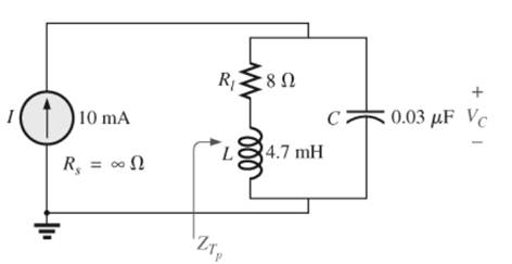
For the parallel resonant network in Fig. 21.55:
a. Calculate fs.
b. Determine Q using
c. Determine fp and fm.
d. Calculate XL and Xc using fp How do they compare?
e. Find the total impedance at resonance (fp).
f. Calculate V at resonance (fp).
g. Determine Q and the BWusing fp.
h. Calculate VL and Ic at fp.
Expert Solution & Answer
Want to see the full answer?
Check out a sample textbook solution
Students have asked these similar questions
A Parallel Resonant ckt is given in the figure. Calculate Wo, W1, W2 , QF & Bw.
7. a. The bandwidth of a series resonant circuit is 200 Hz.
If the resonant frequency is 2000 Hz, what is the
value of Q. for the circuit?
b. If R = 22, what is the value of X₂ at resonance?
c. Find the value of L and C at resonance.
d. Find the cutoff frequencies.
Calculate the gain at -3dB in dB.
Chapter 21 Solutions
Introductory Circuit Analysis (13th Edition)
Ch. 21 - Find the resonant s and fs for the series circuit...Ch. 21 - For the senes circuit in Fig. 21.51 : a. Find the...Ch. 21 - For the senes circuit in Fig. 21.52 : a. Find the...Ch. 21 - For the circuit in Fig. 21.53: a. Find the value...Ch. 21 - a. Find the bandwidth of a series resonant circuit...Ch. 21 - A series circuit has a resonant frequency of 10...Ch. 21 - a. The bandwidth of a series resonant circuit is...Ch. 21 - The cutoff frequencies of a series resonant...Ch. 21 - a. Design a series resonant circuit with an input...Ch. 21 - Design a series resonant circuit to have a...
Ch. 21 - A series resonant circuit is to resonate at s=2106...Ch. 21 - Prob. 12PCh. 21 - For the ideal parallel resonant circuit in Fig. 21...Ch. 21 - For the parallel resonant network in Fig. 21.55:...Ch. 21 - The network of Fig. 21.56 has a supply with an...Ch. 21 - For the network in Fig. 21.57: a. Find the value...Ch. 21 - The network shown in Fig. 21.58 is to resonate at...Ch. 21 - For the network in Fig. 21.59: a. Find the...Ch. 21 - Prob. 19PCh. 21 - It is desired that the impedance ZT of the high Q...Ch. 21 - For the network in Fig. 21.62: a. Find fp. b....Ch. 21 - For the network in Fig. 21.63: a. Find the value...Ch. 21 - Prob. 23PCh. 21 - For the network in Fig. 21.65: a. Find fs. fp, and...Ch. 21 - For the network in Fig. 21.66, the following are...Ch. 21 - Prob. 26PCh. 21 - For the parallel resonant circuit in Fig. 21.68:...Ch. 21 - Verify the results in Example 21.8, That is, show...Ch. 21 - Find fp and fm for the parallel resonant network...
Additional Engineering Textbook Solutions
Find more solutions based on key concepts
How many coulombs do 93.8 1016 electrons represent?
Principles Of Electric Circuits
Three point charges of equal magnitude q, that will yield a zero net electric field at the origin.
Engineering Electromagnetics
With respect to the circuit in Fig. 5.90, (a) employ Thévenin’s theorem to determine the equivalent network see...
Loose Leaf for Engineering Circuit Analysis Format: Loose-leaf
Identify the type of input and output configuration for each diff-amp in Figure 18-35.
Electronics Fundamentals: Circuits, Devices & Applications
Design an ideal inverting op-amp circuit such that the voltage gain is Av=25 . The maximum current in any resis...
Microelectronics: Circuit Analysis and Design
Does the severity of an electric shock increase ordecrease with eh of the following changes? a. A decrease in t...
Electric Motors and Control Systems
Knowledge Booster


Learn more about
Need a deep-dive on the concept behind this application? Look no further. Learn more about this topic, electrical-engineering and related others by exploring similar questions and additional content below.Similar questions
- Calculate the resonant frequency of the median resonator. The value of D2= 6.05 cm, D1= 1.72 cm,Lreal= 1.89 cm and the temperature is 25°. Also obtain the value in units of the frequency ofresonance.arrow_forwardThe resonant converter having fixed value of resonant frequency 48 Hz and capacitance of 2 muF. Find the inductance of this resonant converter a. 2.64 H b. 5.49 H c. 33.12 H d. 34.51 Harrow_forwardd. Determine fLs. fie and flg e. Determine the low cutoff frequency. f. Sketch the asymptotes of the Bode plot defined by the cutoff frequencies of part (d). g. Sketch the low-frequency response for the amplifier using the results of part (e). 14 V Cw, = 5 pF Che = 12 pF Cw, = 8 pF Che = 40 pF Cee = 8 pF 5.6 kM 68 kN 0.47 μ %23 B = 120 0.47 µF 3.3 k2 10 k2 20 µF 1.2 k2 0.47 µF FIG. 9.80 Problems 15, 19, 27, and 38.arrow_forward
- Determine the gain, Vout/ Vin, for the given circuit. What is the resonant frequency of the circuit, in Hertz? + Vout Vinarrow_forward*9. Design a series resonant circuit with an input voltage of 5 V 20° to have the following specifications: a. A peak current of 500 mA at resonance b. A bandwidth of 120 Hz c. A resonant frequency of 8400 Hz Find the value of L and C and the cutoff frequencies.arrow_forwardQ.5: b. Choose the suitable choice for nine of the following sentences. 1. In order to lune a parallel resonant circuit to a lower frequency. the capacitor must........ > Be decrease. a. Be increase d. Remain the same. e. Be Zero. 2 In series as well as parallel resonance circuit, increase in resistance would cause the bandwidth is...... a. Increase in both circuits. (h. Decrease in series eircuit and increase in parallel circuit. d. lucrease in series circuit and decrease in parallel circuit. circuit. e Decrease in both circuits. 3. In a very low frequency a series resonance circuit behaves as almost purely a. Resistive. c. Inductive. d. Inductive and capacitive. b. Capacitive: 4. Real part of the total impedance at resonance for complicated AC circuit is a. Positive Value. b. Zero Value. 5. For admittance locus the maximum obtained power factor is depend on: a. Maximum current b. Maximum voltage c. Minimum power 4. Minimum angle 6. Any non-sinusoidal symmetrical waves are basically…arrow_forward
- P3 For the series RLC circuit given in Figure 4 for Vs=10sinot R=2.2 2, L=100 uH and C=1000 uF a) Obtain the resonant frequency and the half-power frequencies. b) Calculate the quality factor and bandwidth. c) Determine the amplitude of the current at 60, 6 and 02. d) Plot the current amplitude versus frequency e) Use LTSPICE to plot frequency response.arrow_forwardH.W: A resistor of resistance R=1000 2is maintained at 17 °C and it shunted by 100 uH inductor. Determine the ms noise voltage across the inductor over a frequency bandwi dth of: Ans: 182 x10° volt Ans: 9.22 x10 volt Ans: 2.34 x10 volt i) 15.9 kHz ii) i) 159 kHz 1590 kHzarrow_forwardof it H PAGE 29 EEI-ELECTI CKTI FINALCOVERAGE TOPIC AND ASSIGNMENT SERIES RESONANCE (R, L&C CKTS) WHERE: I= CURRENT IN AMPS V:IMPRESSED VOLTAGEN VOIS aL R= RESISTANCEE IN OH MS L= INDUCTANCE IN HENRY C CAPACITANCE IRLFARAD FIGURE RESONANT FREQUENCY FORMULA HZ ASSIENMENT PROBLEM: AN IMPEDANCE COIL HAVING ARESISTANCE AND INDUCTANCE OF 20 AND I.5 MILLLHENRY RESPECTIVELY CONNECTED IN SERIES WITH A CAPACITOR. CALCULATE THE VALUE OF CAPACITANCE IFTHE CKT WILL OPERATE AT RESONANCE.THE RESONANT EREQUENC(to 15 4.5 KHZ.arrow_forward
- Can we obtain a plot of XL against frequency f experimentally?arrow_forwardThe bandwidth of a composite signal is the difference between the highest and a. zero frequency b. lowest frequencies c. two Parallel frequencies d. None of Abovearrow_forward(b) In a filter, explain what happens at the cut–off frequency.arrow_forward
arrow_back_ios
SEE MORE QUESTIONS
arrow_forward_ios
Recommended textbooks for you
 Introductory Circuit Analysis (13th Edition)Electrical EngineeringISBN:9780133923605Author:Robert L. BoylestadPublisher:PEARSON
 Delmar's Standard Textbook Of ElectricityElectrical EngineeringISBN:9781337900348Author:Stephen L. HermanPublisher:Cengage Learning
 Programmable Logic ControllersElectrical EngineeringISBN:9780073373843Author:Frank D. PetruzellaPublisher:McGraw-Hill Education
 Fundamentals of Electric CircuitsElectrical EngineeringISBN:9780078028229Author:Charles K Alexander, Matthew SadikuPublisher:McGraw-Hill Education
 Electric Circuits. (11th Edition)Electrical EngineeringISBN:9780134746968Author:James W. Nilsson, Susan RiedelPublisher:PEARSON
 Engineering ElectromagneticsElectrical EngineeringISBN:9780078028151Author:Hayt, William H. (william Hart), Jr, BUCK, John A.Publisher:Mcgraw-hill Education,
Introductory Circuit Analysis (13th Edition)
Electrical Engineering
ISBN:9780133923605
Author:Robert L. Boylestad
Publisher:PEARSON
Delmar's Standard Textbook Of Electricity
Electrical Engineering
ISBN:9781337900348
Author:Stephen L. Herman
Publisher:Cengage Learning
Programmable Logic Controllers
Electrical Engineering
ISBN:9780073373843
Author:Frank D. Petruzella
Publisher:McGraw-Hill Education
Fundamentals of Electric Circuits
Electrical Engineering
ISBN:9780078028229
Author:Charles K Alexander, Matthew Sadiku
Publisher:McGraw-Hill Education
Electric Circuits. (11th Edition)
Electrical Engineering
ISBN:9780134746968
Author:James W. Nilsson, Susan Riedel
Publisher:PEARSON
Engineering Electromagnetics
Electrical Engineering
ISBN:9780078028151
Author:Hayt, William H. (william Hart), Jr, BUCK, John A.
Publisher:Mcgraw-hill Education,
What is Filter & Classification of Filters | Four Types of Filters | Electronic Devices & Circuits; Author: SimplyInfo;https://www.youtube.com/watch?v=9x1Sjz-VPSg;License: Standard Youtube License