
Introductory Circuit Analysis (13th Edition)
13th Edition
ISBN: 9780133923605
Author: Robert L. Boylestad
Publisher: PEARSON
expand_more
expand_more
format_list_bulleted
Concept explainers
Videos
Textbook Question
Chapter 21, Problem 4P
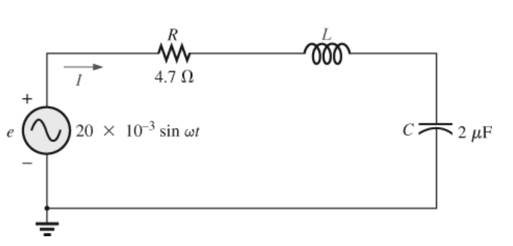
For the circuit in Fig. 21.53:
a. Find the value of L in millihenries if the resonant frequency is 1800 Hz.
b. Calculate XL and Xc How do they compare?
c. Find the magnitude of the current Irms, at resonance.
d. Find the power dissipated by the circuit at resonance.
e. What is the apparent power delivered to the system at resonance?
f. What is the power factor of the circuit at resonance?
g. Calculate the Q of the circuit and the resulting bandwidth.
h. Find the cutoff frequencies. and calculate the power dissipated by the circuit at these frequencies.
Expert Solution & Answer
Want to see the full answer?
Check out a sample textbook solution
Students have asked these similar questions
a. Find the value of L in millihenries if the resonant fre-
quency is 1800 Hz.
b. Calculate X₁ and X. How do they compare?
c. Find the magnitude of the current Irms at resonance.
d. Find the power dissipated by the circuit at resonance.
e. What is the apparent power delivered to the system at
resonance?
f.
What is the power factor of the circuit at resonance?
g. Calculate the Q of the circuit and the resulting bandwidth.
Find the cutoff frequencies, and calculate the power dis-
sipated by the circuit at these frequencies.
h.
R
ww
4.70
20 x 10³ sin wit
voo
C2 μF
1. What is the resonance frequency of ac circuit?
a) 1/VLC
b) v(L/C)
c) VLC
d) LC
21.7 For a series RLC circuit.
a) The bandwidth is 200 Hz. If the resonant frequency is 2000 Hz, what is the value of Q for the circuit?
b) If R = 20, what is the value of X, at resonance?
c) Find the values of L and C at resonance.
d) Determine the cutoff frequencies.
Chapter 21 Solutions
Introductory Circuit Analysis (13th Edition)
Ch. 21 - Find the resonant s and fs for the series circuit...Ch. 21 - For the senes circuit in Fig. 21.51 : a. Find the...Ch. 21 - For the senes circuit in Fig. 21.52 : a. Find the...Ch. 21 - For the circuit in Fig. 21.53: a. Find the value...Ch. 21 - a. Find the bandwidth of a series resonant circuit...Ch. 21 - A series circuit has a resonant frequency of 10...Ch. 21 - a. The bandwidth of a series resonant circuit is...Ch. 21 - The cutoff frequencies of a series resonant...Ch. 21 - a. Design a series resonant circuit with an input...Ch. 21 - Design a series resonant circuit to have a...
Ch. 21 - A series resonant circuit is to resonate at s=2106...Ch. 21 - Prob. 12PCh. 21 - For the ideal parallel resonant circuit in Fig. 21...Ch. 21 - For the parallel resonant network in Fig. 21.55:...Ch. 21 - The network of Fig. 21.56 has a supply with an...Ch. 21 - For the network in Fig. 21.57: a. Find the value...Ch. 21 - The network shown in Fig. 21.58 is to resonate at...Ch. 21 - For the network in Fig. 21.59: a. Find the...Ch. 21 - Prob. 19PCh. 21 - It is desired that the impedance ZT of the high Q...Ch. 21 - For the network in Fig. 21.62: a. Find fp. b....Ch. 21 - For the network in Fig. 21.63: a. Find the value...Ch. 21 - Prob. 23PCh. 21 - For the network in Fig. 21.65: a. Find fs. fp, and...Ch. 21 - For the network in Fig. 21.66, the following are...Ch. 21 - Prob. 26PCh. 21 - For the parallel resonant circuit in Fig. 21.68:...Ch. 21 - Verify the results in Example 21.8, That is, show...Ch. 21 - Find fp and fm for the parallel resonant network...
Knowledge Booster


Learn more about
Need a deep-dive on the concept behind this application? Look no further. Learn more about this topic, electrical-engineering and related others by exploring similar questions and additional content below.Similar questions
- Find the expected frequency, Ei, for the given values of n and pi. n=140, pi=0.6arrow_forwardFind the expected frequency, Ei,for the given values of n and pi. n=180, pi=0.3 Ei= ?arrow_forward21.1 Find the resonant frequency (expressed in Hertz and radians/second, fo and wo) for a series RLC circuit with the following compone nt values: a) R = 102, L = 1H, and C = 16UF b) R = 3002, L = 0.51H, and C = 0.16uF c) R = 202, L = 0.27mH, and C = 7.5uFarrow_forward
- R Vin Vout 1. Find H(w) = Vo/Vi. 2. Derive an expression for the cutoff frequency. 3. Calculate the output voltage at frequencies: 50 Hz, 100 Hz, 150 Hz, 200 Hz, 300 Hz and 1KHZ. Assume Vin=4 v (peak-to-peak), R=1.1 kN and C=1uF. 4. Calculate the cutoff frequency and the output voltage at this value.arrow_forwardVin Vout 1. Find H(w) = Vo/Vi. 2. Derive an expression for the cutoff frequency. 3. Calculate the output voltage at frequencies: 50 Hz, 100 Hz, 150 Hz, 200 Hz, 300 Hz and 1KHZ. Assume Vin=4 v (peak-to-peak), R=1.1 kM and C=1µF. 4. Calculate the cutoff frequency and the output voltage at this value.arrow_forwardThe bandwidth of a composite signal is the difference between the highest and a. zero frequency b. lowest frequencies c. two Parallel frequencies d. None of Abovearrow_forward
- current of 100-µA at resonance. Determine the components and cut-off frequencies.arrow_forwardCapacitor of 30 microfarad capacitance is in series with a coil with 8000 cycle supply. what inductance is required for resonance? ans. 13.19 uHarrow_forward5. QUESTIONS (1) If the inductance in the tank circuit is 80nH and we wish to get a resonance frequency of 100MHZ, what capacitance value of varactor diode should be?arrow_forward
- Is the plot of current versus frequency symmetrical about the resonant frequency? Explainarrow_forwardFor the electric circuit shown in figure below, find the value of the average total power at resonance? * 80cos103t 32 12 + Volt 1mF inarrow_forwardThe cutoff frequencies of a series resonant circuit are 5400 Hz and 6000 Hz. a) Find the bandwidth of the circuit. b) If Qs is 9.5, find the resonant frequency of the circuit. c) If the resistance of the circuit is 2 2 find the value of XL and XC at resonance. d) Find the value of L and C at resonance.arrow_forward
arrow_back_ios
SEE MORE QUESTIONS
arrow_forward_ios
Recommended textbooks for you
 Introductory Circuit Analysis (13th Edition)Electrical EngineeringISBN:9780133923605Author:Robert L. BoylestadPublisher:PEARSON
 Delmar's Standard Textbook Of ElectricityElectrical EngineeringISBN:9781337900348Author:Stephen L. HermanPublisher:Cengage Learning
 Programmable Logic ControllersElectrical EngineeringISBN:9780073373843Author:Frank D. PetruzellaPublisher:McGraw-Hill Education
 Fundamentals of Electric CircuitsElectrical EngineeringISBN:9780078028229Author:Charles K Alexander, Matthew SadikuPublisher:McGraw-Hill Education
 Electric Circuits. (11th Edition)Electrical EngineeringISBN:9780134746968Author:James W. Nilsson, Susan RiedelPublisher:PEARSON
 Engineering ElectromagneticsElectrical EngineeringISBN:9780078028151Author:Hayt, William H. (william Hart), Jr, BUCK, John A.Publisher:Mcgraw-hill Education,
Introductory Circuit Analysis (13th Edition)
Electrical Engineering
ISBN:9780133923605
Author:Robert L. Boylestad
Publisher:PEARSON
Delmar's Standard Textbook Of Electricity
Electrical Engineering
ISBN:9781337900348
Author:Stephen L. Herman
Publisher:Cengage Learning
Programmable Logic Controllers
Electrical Engineering
ISBN:9780073373843
Author:Frank D. Petruzella
Publisher:McGraw-Hill Education
Fundamentals of Electric Circuits
Electrical Engineering
ISBN:9780078028229
Author:Charles K Alexander, Matthew Sadiku
Publisher:McGraw-Hill Education
Electric Circuits. (11th Edition)
Electrical Engineering
ISBN:9780134746968
Author:James W. Nilsson, Susan Riedel
Publisher:PEARSON
Engineering Electromagnetics
Electrical Engineering
ISBN:9780078028151
Author:Hayt, William H. (william Hart), Jr, BUCK, John A.
Publisher:Mcgraw-hill Education,
What is Filter & Classification of Filters | Four Types of Filters | Electronic Devices & Circuits; Author: SimplyInfo;https://www.youtube.com/watch?v=9x1Sjz-VPSg;License: Standard Youtube License