
Introductory Circuit Analysis (13th Edition)
13th Edition
ISBN: 9780133923605
Author: Robert L. Boylestad
Publisher: PEARSON
expand_more
expand_more
format_list_bulleted
Concept explainers
Videos
Textbook Question
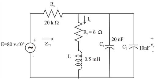
Chapter 21, Problem 24P
For the network in Fig. 21.65:
a. Find fs. fp, and fm.
b. Determine Q1 and Qp at fp after a source conversion is performed.
c. Find the input impedance
d. Find the magnitude of the voltage Vc.
e. Calculate the bandwidth using fp.
f. Determine the magnitude of the currents Ic and I1.
Expert Solution & Answer
Want to see the full answer?
Check out a sample textbook solution
Students have asked these similar questions
Can we obtain a plot of XL against frequency f experimentally?
21.7 For a series RLC circuit.
a) The bandwidth is 200 Hz. If the resonant frequency is 2000 Hz, what is the value of Q for the circuit?
b) If R = 20, what is the value of X, at resonance?
c) Find the values of L and C at resonance.
d) Determine the cutoff frequencies.
LAB 1
Questions
R
Vout
Vin
1. Find H(w) = Vo/Vi.
2. Derive an expression for the cutoff frequency.
3. Calculate the output voltage at frequencies: 50 Hz, 100 Hz, 150 Hz, 200 Hz,
300 Hz and 1KHZ. Assume Vin=4 v (peak-to-peak), R=1.1 k and C=1uF.
4. Calculate the cutoff frequency and the output voltage at this value.
Chapter 21 Solutions
Introductory Circuit Analysis (13th Edition)
Ch. 21 - Find the resonant s and fs for the series circuit...Ch. 21 - For the senes circuit in Fig. 21.51 : a. Find the...Ch. 21 - For the senes circuit in Fig. 21.52 : a. Find the...Ch. 21 - For the circuit in Fig. 21.53: a. Find the value...Ch. 21 - a. Find the bandwidth of a series resonant circuit...Ch. 21 - A series circuit has a resonant frequency of 10...Ch. 21 - a. The bandwidth of a series resonant circuit is...Ch. 21 - The cutoff frequencies of a series resonant...Ch. 21 - a. Design a series resonant circuit with an input...Ch. 21 - Design a series resonant circuit to have a...
Ch. 21 - A series resonant circuit is to resonate at s=2106...Ch. 21 - Prob. 12PCh. 21 - For the ideal parallel resonant circuit in Fig. 21...Ch. 21 - For the parallel resonant network in Fig. 21.55:...Ch. 21 - The network of Fig. 21.56 has a supply with an...Ch. 21 - For the network in Fig. 21.57: a. Find the value...Ch. 21 - The network shown in Fig. 21.58 is to resonate at...Ch. 21 - For the network in Fig. 21.59: a. Find the...Ch. 21 - Prob. 19PCh. 21 - It is desired that the impedance ZT of the high Q...Ch. 21 - For the network in Fig. 21.62: a. Find fp. b....Ch. 21 - For the network in Fig. 21.63: a. Find the value...Ch. 21 - Prob. 23PCh. 21 - For the network in Fig. 21.65: a. Find fs. fp, and...Ch. 21 - For the network in Fig. 21.66, the following are...Ch. 21 - Prob. 26PCh. 21 - For the parallel resonant circuit in Fig. 21.68:...Ch. 21 - Verify the results in Example 21.8, That is, show...Ch. 21 - Find fp and fm for the parallel resonant network...
Knowledge Booster


Learn more about
Need a deep-dive on the concept behind this application? Look no further. Learn more about this topic, electrical-engineering and related others by exploring similar questions and additional content below.Similar questions
- QI/For the BJT amplifier circuit shown in figure with the following parameter: Ch-36PF, C-4pF, Ce=1 pF,Cw 6pF,Cw-8pF and roo .Determine 1-fi.fu.BW.fa and fr . 2-sketch the frequency response. 20 V 3K Ohm 10 UF 200 k Ohm HH 20 uF 1 K Ohm HH 10 k Ohm B=100 100 V 1.5K Ohr 30arrow_forwardDesign (only the block diagram) an Armstrong indirectly FM modulator to generate an FM carrier with a carrier frequency of 98.1MHz and df (frequency deviation) =75kHz.A narrowband FM generator is available at a carrier frequency of 100 KHz and a (frequency deviation) df=10Hz.The stockroom has an oscillator with an adjustable frequency in the range of 10 to 11MHz.There are plenty of Frequency multipliers.arrow_forwardPlease design it using Am or fm or pm or ssb or dsb-scarrow_forward
- Determine gm0 and gm. b. Find Av and Avs in the mid-frequency range. c. Determine the Miller input and output capacitances for the amplifier. d. Determine fHi and fHo. 2. +10 V Ciss = 10 pF Cn =3 pF Iass = 18 nA @ Vos =-10 V Vaston =-8 V Ipss = 10 mA 1.0 kM 0.001 µF 0001 μ 10 kn 50 N 10 ΜΩ 1.0 kfn : 0.1 µFarrow_forwardFind the resonant frequency for the network below. The circuit is energized by a 24-Vac,variable frequency supply. Then, for the resonant condition calculate the circuitimpedance and current.arrow_forwardFor the network of figure below: a. Find Avmid = Vo / Vi. b. Determine fs, fic. and fig. c. Determine the low cutoff frequency. d. Sketch the asymptotes of the Bode plot defined by the low cutoff frequency of part (c). e. Sketch the low-frequency response for the amplifier using the results of part (d) 20Varrow_forward
- Find the frequency of operation [rad/sec] and the relationship between R and Rf for the Phase Shift Oscillator circuit shown below: Rf C C H V. R Rarrow_forwardd. Determine fLs. fie and flg e. Determine the low cutoff frequency. f. Sketch the asymptotes of the Bode plot defined by the cutoff frequencies of part (d). g. Sketch the low-frequency response for the amplifier using the results of part (e). 14 V Cw, = 5 pF Che = 12 pF Cw, = 8 pF Che = 40 pF Cee = 8 pF 5.6 kM 68 kN 0.47 μ %23 B = 120 0.47 µF 3.3 k2 10 k2 20 µF 1.2 k2 0.47 µF FIG. 9.80 Problems 15, 19, 27, and 38.arrow_forward: Calculate the corner frequency and maximum gain of a bipolar common-emitter Cırcuit with a coupling capacitor. For the circuit shown in Figure, the parameters are: R = 51.2 KA, R2 =9.6K2, R. = 2KN, RE =0.4K2, R =0.1KN, C. = 1µF, Vec = 10V, B-100, gm =69.6mA/V and r, =1.44KO. Vce Re Rs RE ww wwHarrow_forward
- For the following given circuit; b) find Av and Avs in the medium frequency range.c) find fHi and fh0.d) draw the frequency response for the high frequency region using the bode graph and determine the cutting frequency.arrow_forwardWhich of the following diode is used in high frequency switching operations? O a. General purpose diode O b. Schottky diode PN junction diode O d. Şilicon junction diode Choose the % derating factor of the string which is having 9 number of SCR connected in series to withstand a DC voltage of 1733 V and steady state voltage rating of 896 V. O a. 78.51 O b. 10.75 Oc. 21.49 O d. 5.74 o searcharrow_forward21.3 For the series circuit in Fig. 21.52: + VE R = 100 A E 12 V 2 kl V d) Determine the quality factor of the circuit. Is it a high- or low-Q circuit? e) If the resonant frequency is 5 kHz, determine the value of L and C. f) Find the bandwidth of the response if the resonant frequency is 5 kHz. g) What are the low and high cutoff frequencies?arrow_forward
arrow_back_ios
SEE MORE QUESTIONS
arrow_forward_ios
Recommended textbooks for you
 Power System Analysis and Design (MindTap Course ...Electrical EngineeringISBN:9781305632134Author:J. Duncan Glover, Thomas Overbye, Mulukutla S. SarmaPublisher:Cengage Learning
Power System Analysis and Design (MindTap Course ...
Electrical Engineering
ISBN:9781305632134
Author:J. Duncan Glover, Thomas Overbye, Mulukutla S. Sarma
Publisher:Cengage Learning
What is Filter & Classification of Filters | Four Types of Filters | Electronic Devices & Circuits; Author: SimplyInfo;https://www.youtube.com/watch?v=9x1Sjz-VPSg;License: Standard Youtube License