
Fluid Mechanics: Fundamentals and Applications
4th Edition
ISBN: 9781259696534
Author: Yunus A. Cengel Dr., John M. Cimbala
Publisher: McGraw-Hill Education
expand_more
expand_more
format_list_bulleted
Concept explainers
Videos
Textbook Question
Chapter 14, Problem 24P
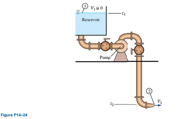
Consider the flow system sketched in Fig. PI 4-24. The fluid is water, and the pump is a centrifugal pump. Generate a qualitative plot of the pump net head as a function of the pump capacity. On the figure, label the shutoff head, the free delivery, the pump performance curve, the system curve, and the operating point. (Hint: Carefully consider the required net head at conditions of zero flow rate.)
Expert Solution & Answer
Want to see the full answer?
Check out a sample textbook solution
Students have asked these similar questions
Consider the flow system sketched in Fig. The fluid is water, and the pump is a centrifugal pump. Generate a qualitative plot of the pump net head as a function of the pump capacity. On the figure, label the shutoff head, the free delivery, the pump performance curve, the system curve, and the operating point
Answer with True or False of the following question:
(7M
1. Water flows steadily down a vertical pipe of constant cross section. Neglecting friction, according
to Bernoulli's equation, velocity decreases with height.
2. A liquid in an open right circular cylinder is given rigid body rotation about the axis of the
cylinder. The pressure distribution in any vertical plane is uniform.
3. A curved surface is submerged in a static liquid. The horizontal component of pressure force on it
is equal to the pressure force on a vertical projection of the surface.
4. A U-tube manometer measures the difference in total energy between two points.
solve 20-30 mins i'll give you multiple upvote( handwritten asap)How can I solve the problem below in viscous fluid flow?
Chapter 14 Solutions
Fluid Mechanics: Fundamentals and Applications
Ch. 14 - What is the more common term for an...Ch. 14 - What the primary differences between fans,...Ch. 14 - List at least two common examples of fans, of...Ch. 14 - Discuss the primary difference between a porn...Ch. 14 - Explain why there is an “extra” term in the...Ch. 14 - For a turbine, discuss the difference between...Ch. 14 - Prob. 7CPCh. 14 - Prob. 8PCh. 14 - Prob. 9PCh. 14 - Prob. 10CP
Ch. 14 - There are three main categories of dynamic pumps....Ch. 14 - For each statement about cow cetrifugal the...Ch. 14 - Prob. 13CPCh. 14 - Consider flow through a water pump. For each...Ch. 14 - Write the equation that defines actual (available)...Ch. 14 - Consider a typical centrifugal liquid pump. For...Ch. 14 - Prob. 17CPCh. 14 - Consider steady, incompressible flow through two...Ch. 14 - Prob. 19CPCh. 14 - Prob. 20PCh. 14 - Suppose the pump of Fig. P1 4-19C is situated...Ch. 14 - Prob. 22PCh. 14 - Prob. 23EPCh. 14 - Consider the flow system sketched in Fig. PI 4-24....Ch. 14 - Prob. 25PCh. 14 - Repeat Prob. 14-25, but with a rough pipe-pipe...Ch. 14 - Consider the piping system of Fig. P14—24. with...Ch. 14 - The performance data for a centrifugal water pump...Ch. 14 - For the centrifugal water pump of Prob. 14-29,...Ch. 14 - Suppose the pump of Probs. 14-29 and 14-30 is used...Ch. 14 - Suppose you are looking into purchasing a water...Ch. 14 - The performance data of a water pump follow the...Ch. 14 - For the application at hand, the flow rate of...Ch. 14 - A water pump is used to pump water from one large...Ch. 14 - For the pump and piping system of Prob. 14-35E,...Ch. 14 - A water pump is used to pump water from one large...Ch. 14 - Suppose that the free surface of the inlet...Ch. 14 - Calculate the volume flow rate between the...Ch. 14 - Comparing the results of Probs. 14-39 and 14-43,...Ch. 14 - Prob. 45PCh. 14 - The performance data for a centrifugal water pump...Ch. 14 - Transform each column of the pump performance data...Ch. 14 - 14-51 A local ventilation system (a hood and duct...Ch. 14 - Prob. 52PCh. 14 - Repeat Prob. 14-51, ignoring all minor losses. How...Ch. 14 - Suppose the one- way of Fig. P14-51 malfunctions...Ch. 14 - A local ventilation system (a hood and duct...Ch. 14 - For the duct system and fan of Prob. 14-55E,...Ch. 14 - Repeat Prob. 14-55E, ignoring all minor losses....Ch. 14 - A self-priming centrifugal pump is used to pump...Ch. 14 - Repeat Prob. 14-60. but at a water temperature of...Ch. 14 - Repeat Prob. 14-60, but with the pipe diameter...Ch. 14 - Prob. 63EPCh. 14 - Prob. 64EPCh. 14 - Prob. 66PCh. 14 - Prob. 67PCh. 14 - Prob. 68PCh. 14 - Prob. 69PCh. 14 - Two water pumps are arranged in Series. The...Ch. 14 - The same two water pumps of Prob. 14-70 are...Ch. 14 - Prob. 72CPCh. 14 - Name and briefly describe the differences between...Ch. 14 - Discuss the meaning of reverse swirl in reaction...Ch. 14 - Prob. 75CPCh. 14 - Prob. 76CPCh. 14 - Prob. 77PCh. 14 - Prob. 78PCh. 14 - Prob. 79PCh. 14 - Prob. 80PCh. 14 - Wind ( =1.204kg/m3 ) blows through a HAWT wind...Ch. 14 - Prob. 82PCh. 14 - Prob. 84CPCh. 14 - A Francis radial-flow hydroturbine has the...Ch. 14 - Prob. 87PCh. 14 - Prob. 88PCh. 14 - Prob. 89PCh. 14 - Prob. 90CPCh. 14 - Prob. 91CPCh. 14 - Discuss which dimensionless pump performance...Ch. 14 - Prob. 93CPCh. 14 - Prob. 94PCh. 14 - Prob. 95PCh. 14 - Prob. 96PCh. 14 - Prob. 97PCh. 14 - Prob. 98PCh. 14 - Prob. 99PCh. 14 - Prob. 100EPCh. 14 - Prob. 101PCh. 14 - Calculate the pump specific speed of the pump of...Ch. 14 - Prob. 103PCh. 14 - Prob. 104PCh. 14 - Prob. 105PCh. 14 - Prob. 106PCh. 14 - Prob. 107EPCh. 14 - Prob. 108PCh. 14 - Prob. 109PCh. 14 - Prob. 110PCh. 14 - Prove that the model turbine (Prob. 14-109) and...Ch. 14 - Prob. 112PCh. 14 - Prob. 113PCh. 14 - Prob. 114PCh. 14 - Prob. 115CPCh. 14 - Prob. 116CPCh. 14 - Prob. 117CPCh. 14 - Prob. 118PCh. 14 - For two dynamically similar pumps, manipulate the...Ch. 14 - Prob. 120PCh. 14 - Prob. 121PCh. 14 - Prob. 122PCh. 14 - Calculate and compare the turbine specific speed...Ch. 14 - Prob. 124PCh. 14 - Prob. 125PCh. 14 - Prob. 126PCh. 14 - Prob. 127PCh. 14 - Prob. 128PCh. 14 - Prob. 129PCh. 14 - Prob. 130PCh. 14 - Prob. 131PCh. 14 - Prob. 132PCh. 14 - Prob. 133PCh. 14 - Prob. 134PCh. 14 - Prob. 135PCh. 14 - A two-lobe rotary positive-displacement pump moves...Ch. 14 - Prob. 137PCh. 14 - Prob. 138PCh. 14 - Prob. 139PCh. 14 - Prob. 140PCh. 14 - Which choice is correct for the comparison of the...Ch. 14 - Prob. 142PCh. 14 - In a hydroelectric power plant, water flows...Ch. 14 - Prob. 144PCh. 14 - Prob. 145PCh. 14 - Prob. 146PCh. 14 - Prob. 147PCh. 14 - Prob. 148PCh. 14 - Prob. 149PCh. 14 - Prob. 150PCh. 14 - Prob. 151P
Knowledge Booster


Learn more about
Need a deep-dive on the concept behind this application? Look no further. Learn more about this topic, mechanical-engineering and related others by exploring similar questions and additional content below.Similar questions
- P (6-5) Two centrifugal pumps are connected in parallel in a given pumping system. Plot total head Ah against capacity Q pump and system curves for both pumps running on the basis of the following data: Operating data for pump 1 Operating data for pump 2 Ahm, 40.0 35.0 30.0 25.0 Ah m. 0.0 35 30 25 Qim³/h. 169 209 239 265 Q₂m/h 0 136 203 267 data for system Ah m, 20.0 25.0 30.0 35.0 Q.m³/h, 0 244 372 470arrow_forwardExample (1-2): A pump delivers water from a tank A (water surface elevation =110 m) to tank B (water surface elevation = 170 m). The suction pipe is 45 m long (friction factor, f = 0-024) and 35 cm in diameter. The delivery pipe is 950 m long (f = 0·022) and 25 cm in diameter. The head discharge relationship for the pump is given by Hp = (90 – 8000 Q²), where Hp is in metres and Q in m³/s. Calculate: (i) The discharge in the pipeline. (ii) The power delivered by the pump.arrow_forwardBOOK: FLUID POWER, 3e, JAMES A. SULLIVAN PROBLEM: 10 - 4arrow_forward
- a 4 Exercise 7 -Opening and closing a boiler door for b) Calculate retracting speed, retracting time, travel speed ratio and travel time ratio. ictin Characteristic data required for calculation: Piston surface area: Ap = 2.0 sq. cm Piston ring surface area: APR = 1.2 sq. cm Stroke length: = 200 mm S Pump delivery rate: = 2 l/min b Retracting speed Retracting time Travel speed ratio Travel time ratioarrow_forwardExample (1-3): A jet of water 8 cm in diameter moving with velocity of 12 m/s strikes a flat vane which is normal to the axis of the stream. (a) Find the force exerted by the jet if the vane moves with a velocity of 5 m/s. (b) Determine the force exerted by the jet if instead of one flat vane, there is a series of vanes so arranged that each vane appears successively before the jet in the same position and always moving with a velocity of 5 m/s. (c) Determine also the efficiency of the system.arrow_forward1) The velocity profile of a viscus fluid over a plate is parabolie with vertex 25 em from the plate ,where the velocity 125 cm/s. calculate the velocity gradient and shear stress at distance of (0, 5, 15 and 25 cm) from the plate given the viscosity of the fluid =7 poise ? Also draw the figure explain the relationship between the velocity gradient and shear stress. Take velocity profile for parabolic equation, (v = ay + by + c)arrow_forward
- 338 B/s O 1: 56% E 3:01 Question: Gasoline is flowing through this 180° pipe bend. The pipe cross-sectional area is 18 in?. Take the pipe weight as 5 Kg. Flow rate is 0.5 liters/s. Pressure at section-1 6 psia, pressure at section-2 is 4 psia. Calculate the anchoring force required to hold this pipe and also show its direction, referenced to proper 2-dimensional a cartesian coordinate system. (2 1arrow_forwardDirections: In any clean sheet of paper, write your name, solve the problem and show your solution. Box your final answer. Take a picture of it and upload it here (image/pdf). 1) Between two sections in a vessel, a fluid moves in a steady flow manner. At entrance: A1=20 m2, P1=1300 kgm/m3. At exit: A2-10 m2, 02=0.00125 m /kg, Ü2=3 m/min. Determine the following: a) m, in kg/min b) Ủz in m/minarrow_forwardThe pump shown on the figure below has characteristic curves shown in the graph. Estimate the flow rate and, a) Calculate the pump power requirement b) Calculate the pressure at the pump inlet & outlet c) Sketch the EGL & HGL Water 10°C € 20 m 16-cm-dia. wrought iron pipe 10 m I 10 m 30 m 8 m 10 m Water 20°C Hp (m) 80 60 40 20 Hp 0.1 0.2 Q (m³/s) 0.3 ПР 80 60 40 20 ПРarrow_forward
- Nadeen is washing her car, using a nozzle similar to the one sketched in Fig. 4-8. The nozzle is 3.90 in (0.325 ft) long, with an inlet diameter of 0.420 in (0.0350 ft) and an outlet diameter of 0.182 in (see Fig. 4–9). The volume flow rate through the garden hose (and through the nozzle) is V = 0.841 gal/min (0.00187 ft/s), and the flow is steady. Estimate the magnitude of the acceleration of a fluid particle moving down the centerline of the nozzle.arrow_forwardSimulation of laminar gas flow in the pipe with Ansys Fluent Task: 1. Calculate velocity distribution in y axis at inlet and outlet of the pipe. Submit it as a chart. 2. Calculate velocity distribution over the pipe length. Submit it as a chart. Figure. pipe geometry L, m = 16 R, m= 0.15 Inlet velocity, m/s= 0.08 Gas= Oxygen Need proper solution like pdf file, don't need steps by steps. If you can can do it through ansys fluent. Write proper solution on word file or pdf.arrow_forwardimage attached. Note: Pump characteristics are in the table circled in yellow. Note: maximum efficiency ( nm)= 0.7arrow_forward
arrow_back_ios
SEE MORE QUESTIONS
arrow_forward_ios
Recommended textbooks for you
 Elements Of ElectromagneticsMechanical EngineeringISBN:9780190698614Author:Sadiku, Matthew N. O.Publisher:Oxford University Press
 Mechanics of Materials (10th Edition)Mechanical EngineeringISBN:9780134319650Author:Russell C. HibbelerPublisher:PEARSON
 Thermodynamics: An Engineering ApproachMechanical EngineeringISBN:9781259822674Author:Yunus A. Cengel Dr., Michael A. BolesPublisher:McGraw-Hill Education
 Control Systems EngineeringMechanical EngineeringISBN:9781118170519Author:Norman S. NisePublisher:WILEY
 Mechanics of Materials (MindTap Course List)Mechanical EngineeringISBN:9781337093347Author:Barry J. Goodno, James M. GerePublisher:Cengage Learning
 Engineering Mechanics: StaticsMechanical EngineeringISBN:9781118807330Author:James L. Meriam, L. G. Kraige, J. N. BoltonPublisher:WILEY
Elements Of Electromagnetics
Mechanical Engineering
ISBN:9780190698614
Author:Sadiku, Matthew N. O.
Publisher:Oxford University Press
Mechanics of Materials (10th Edition)
Mechanical Engineering
ISBN:9780134319650
Author:Russell C. Hibbeler
Publisher:PEARSON
Thermodynamics: An Engineering Approach
Mechanical Engineering
ISBN:9781259822674
Author:Yunus A. Cengel Dr., Michael A. Boles
Publisher:McGraw-Hill Education
Control Systems Engineering
Mechanical Engineering
ISBN:9781118170519
Author:Norman S. Nise
Publisher:WILEY
Mechanics of Materials (MindTap Course List)
Mechanical Engineering
ISBN:9781337093347
Author:Barry J. Goodno, James M. Gere
Publisher:Cengage Learning
Engineering Mechanics: Statics
Mechanical Engineering
ISBN:9781118807330
Author:James L. Meriam, L. G. Kraige, J. N. Bolton
Publisher:WILEY
Fluid Mechanics - Viscosity and Shear Strain Rate in 9 Minutes!; Author: Less Boring Lectures;https://www.youtube.com/watch?v=_0aaRDAdPTY;License: Standard youtube license