
Concept explainers
Videos
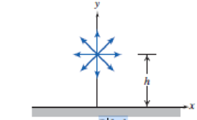
Carefully sketch the energy grade lines (EGL) and hydraulic grade lines (HGL) for the system shown in Fig. 6.6 if the pipe is horizontal (i.e., the outlet is at the base of the reservoir), and a water turbine (extracting energy) is located at point ②, or at point ③. In Chapter 8 we will investigate the effects of friction on internal flows. Can you anticipate and sketch the effect of friction on the EGL and HGL for the two cases?
P6.6
Want to see the full answer?
Check out a sample textbook solution
Chapter 6 Solutions
Fox and McDonald's Introduction to Fluid Mechanics
Additional Engineering Textbook Solutions
Starting Out with Programming Logic and Design (5th Edition) (What's New in Computer Science)
Computer Science: An Overview (13th Edition) (What's New in Computer Science)
Concepts Of Programming Languages
Thermodynamics: An Engineering Approach
Electric Circuits. (11th Edition)
Starting Out with Java: From Control Structures through Objects (7th Edition) (What's New in Computer Science)


- can someone explain 67. Also how do you figure out which to use sine or cosine in this?arrow_forwardQ10 An ideal Diesel engine has a compression ratio of (20) and uses air as the working fluid. The state of air at the beginning of the compression process is (95 KPa) and (20 °C). If the maximum temperature in the cycle is not to exceed (2200K), determine அ عماد داود عبودarrow_forwardComplete fbd. The e is inclined.arrow_forward
- The parabolic cable running between the two transmission towers is carrying a uniformly distributed load of 15 kN/m over a span of L = 20 m with a sag of y = 5 m. The left end of the cable is connected at point F as shown in the spot detail. The protruding members of the transmission tower is to be analyzed assuming pin connection at joints A and K. Given: a = 1.2 m, b = 0.8 m, c = 1.0 m, d = 0.6 m, and e = 0.3 m. Calculate the following with complete fbd: indicate if in compression or tension on the membersa. Maximum and minimum tension of the cable, in kN.b. Length of the cable, in m.arrow_forwardQ8 In an ideal Diesel cycle the pressure and temperature at the beginning of compression are (98.5 KN/m²) and (60 °C) respectively. The maximum pressure attained during the cycle is (4.5 MN/m²) and the heat received during the cycle is (850 Kj/Kg) of working fluid. Determine (a) the compression ratio. (b) the temperature at the end of compression and (c) the temperature at the end combustion. Answers (a) 15.3, (b) 989 K, (c) 1566 Karrow_forwardQ9 An air-standard cycle is executed in a closed system with (0.002 Kg) of air, and it consists of the following three processes : 1-2 Isentropic compression from (100 KPa) and (27 °C) to (700 KPa). 2-3 P=constant heat addition to initial specific volume. 3-1 v constant heat rejection to initial state. (a) Show the cycle on P-v and T-s diagram. (b) Calculate the maximum temperature in the cycle. Answer T3 = 2100 K (c) Determine the thermal efficiency. Answer 18.5%arrow_forward
- help me solve pleasearrow_forwardPart A The block is supported by the short link BD, the ball-and-socket joint A, and cords CE, CF. Suppose that F₁ =5 kN and F2 = 8.5 kN. (Figure 1) Determine the z component of reaction force at B using scalar notation. Express your answer to three significant figures and include the appropriate units. 미 μA ? B₂ = Value Units Submit Previous Answers Request Answer × Incorrect; Try Again Part B Determine the tension in the cord CE. Express your answer to three significant figures and include the appropriate units. μA ? Units FCE= Value Submit Previous Answers Request Answer × Incorrect; Try Againarrow_forwardLearning Goal: To analyze a rod assembly in three-dimensional space and determine the support reactions by using the equations of equilibrium for a rigid body. The rod assembly shown has smooth journal bearings at A, B, and C. The forces F₁ = 650 N, F₂ = 560 N, F3 = 430 N, and F₁ = 925 N are applied as shown in the figure. The geometry of the rod assembly is given as a = 0.900 m, b=0.600 m, and c = 0.650 m. Neglect the weight of the rod. Determine the 2 component of the reaction exerted on the rod at C. Express your answer to three significant figures and include the appropriate units. ▸ View Available Hint(s) НА ? Cz = Value Units x A B FA Submit Previous Answers × Incorrect; Try Again - Part C - Finding the z component of the reaction at B Determine the component of the reaction on the rod at B. Express your answer to three significant figures and include the appropriate units. ▸ View Available Hint(s) μA B₂ = Value Units Submit Previous Answers × Incorrect; Try Again ? Part D -…arrow_forward
 Elements Of ElectromagneticsMechanical EngineeringISBN:9780190698614Author:Sadiku, Matthew N. O.Publisher:Oxford University Press
 Mechanics of Materials (10th Edition)Mechanical EngineeringISBN:9780134319650Author:Russell C. HibbelerPublisher:PEARSON
 Thermodynamics: An Engineering ApproachMechanical EngineeringISBN:9781259822674Author:Yunus A. Cengel Dr., Michael A. BolesPublisher:McGraw-Hill Education
 Control Systems EngineeringMechanical EngineeringISBN:9781118170519Author:Norman S. NisePublisher:WILEY
 Mechanics of Materials (MindTap Course List)Mechanical EngineeringISBN:9781337093347Author:Barry J. Goodno, James M. GerePublisher:Cengage Learning
 Engineering Mechanics: StaticsMechanical EngineeringISBN:9781118807330Author:James L. Meriam, L. G. Kraige, J. N. BoltonPublisher:WILEY