
Videos
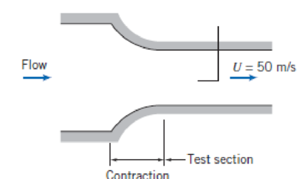
The inlet contraction and test section of a laboratory wind tunnel are shown. The air speed in the test section is U = 50 m/s. A total-head tube pointed upstream indicates that the stagnation pressure on the test section centerline is 10 mm of water below atmospheric. The laboratory is maintained at atmospheric pressure and a temperature of −5°C. Evaluate the dynamic pressure on the centerline of the wind tunnel test section. Compute the static pressure at the same point. Qualitatively compare the static pressure at the tunnel wall with that at the centerline. Explain why the two may not be identical.
P6.33
Want to see the full answer?
Check out a sample textbook solution
Chapter 6 Solutions
Fox and McDonald's Introduction to Fluid Mechanics
Additional Engineering Textbook Solutions
Automotive Technology: Principles, Diagnosis, and Service (5th Edition)
Applied Fluid Mechanics (7th Edition)
Heating Ventilating and Air Conditioning: Analysis and Design
Thinking Like an Engineer: An Active Learning Approach (3rd Edition)
Fundamentals of Heat and Mass Transfer
Engineering Mechanics: Statics


- Derive the dynamic equation in terms of the height h for the following fluid system. Assume laminar flow in the orifice. Assume p to be density of the fluid and g gravity. a is the area of the pipe. A H -Pi+Pa R L Paarrow_forwardWater is flowing out of the nozzle (2) into atmospheric pressure (101 kPa). What is the gauge pressure at point (1), when flow rate is 32.18 m3/h and frictional losses are ignored? Water density is 1000 kg/m3.arrow_forwardQUESTION 2 Water flows through the horizontal branching pipe shown in Figure 3. Water discharges into the atmosphere at section (4). If viscous effects are negligible, a) determine the pressure at section (2). b) calculate the velocity at section (3). c) what is the x component of the anchoring force at the flange to hold the pipe in place? Draw the control volume and identify all forces. A2 = 0.007 m² V2 = 9 m/s (1) Flange 40° A = 0.1 m² V, = 3 m/s → P, = 69 kPa Az = 0.02 m² %3D P3 = 55 kPa (3) A4 = 0.0095 m². (4) Figure 3arrow_forward
- A pump test for air flow is set up as shown below in which the pump draws air from the atmosphere into the 1-ft diameter pipe. The liquid in the differential manometer is water (? = 62.4 ?b/??^3) and the density of air is 0.00238 ?lug/??^3. Assume that the air flow is incompressible and frictionless. (a) Using the piezometer tube, compute the pressure in the pipe. (b) Using the Pitot tube and an energy equation, compute the velocity in the pipe. (c) Assuming that the air far away from the entrance to the pump is at rest (zero velocity), calculate the power delivered by the pump.arrow_forwardConsider the wind tunnel shown below. The diameter at section 1 is 0.9 m and the diameter at section 2 is 0.4 m. A manometer is used to determine the pressure difference between the two sections. The manometer liquid has a specific gravity of 0.82. Determine the change in height in the manometer if the velocity at section 2 is 66 m/s. Assume incompressible flow and standard sea-level conditions. Provide answer in centimeters. Round-off answer to the nearest whole number.arrow_forwardWater steam is running through the nozzle. Inlet pressure is P1=25 bars; T1=300C; V1=90m/s; A1=0.2m2. The exit parameters are: P2=11bars; T2=210C. The mass flow rate is m=2 kg/s. Determine: a.Exit velocity V2=?; b.Inlet and outlet diameters D1 and D2.arrow_forward
- The airduct shown below has a slanted exit, the dimension of which is 2 inch by 3 inch. Air is flowing out of the duct at a velocity of 6 ft/s, 45° to the surface of the exit. Pressure is 1 bar (14.7 psia) and temperature is 60 °F. Please compute • Density of air at this pressure and temperature; • Mass rate-of-flow through the duct; • Momentum rate-of-flow through the duct along the direction of air flow. 3 in. Air flow 6 ft/s 2 in. Side view 45°arrow_forwardA horizontal nozzle discharges water into the atmosphere as shown in the figure. the relative pressure at point 1 equal to p1 = 18 kPa. a. A Pitot tube connected to a mercury manometer is inserted into the flow. in the area section A1 indicating a height difference h = 0.01 m. For this reading indicated in the Pitot tube, determine the velocity in the A1 area section of the nozzle. b. For the dimensioning of the anchor block it is necessary to determine the force that the nozzle applies over the fluid. Calculate the component of this force in the x direction. Data: D1 = 0.070 m; D2 = 0.060 m; 0 = 30°; dHg = 13.6 Patm A2 pi Fx A1 Block of anchoragearrow_forwardcontoured nozzle. In the test section, where the flow is straight and nearly uniform, a static pressure tap is drilled into the tunnel wall. A manometer connected to the tap shows that the static pressure within the tunnel is 45 mm of water below atmosphere. Assume that air is incompressible and at pressure is 100 kPa (absolute). Calculate the velocity in the wind tunnel section (Refer to Fig. 6.6). Density of P. 100 kPa water is 999 kg/m' and characteristic gas constant for V-0 air is 287 J/kg K. 25°C, O Test section 25°C (GATE) To manometer Fig. 6.6arrow_forward
- The venturi nozzle in the airflow experiment measures a static pressure of 7 psf (lb/ft2 ) before the nozzle and a static pressure of 2 psf after the nozzle. If the Reynolds Number of the flow is 5.7E+04, gc = 32.17 lmm-ft/lbf -s2 , ρ = 0.075 lbm/f t3 Dpipe = 5 in, and Dventuri = 2.74 in, find the flow rate in the pipe. Present answer in cfm.arrow_forwardwhat will be the pressure gradient (kpa/m) at L=30 cm through the nozzle? At L=0, the liquid flows inside the nozzle has a specific gravity S=6.1, at L=0, the velocity is 2 m/s while at L=70 cm, the velocity is 6 m/s. Assume steady and inviscid flow. The velocity varies linearly with distance through the nozzle. 70 cm 60 em Liguidarrow_forward4. A pipe carries oil of density 800 kg/m³. At a given point (1) the pipe has a bore area of 0.005 m² and the oil flows with a mean velocity of 4 m/s with a gauge pressure of 800 kPa. Point (2) is further along the pipe and there the bore area is 0.002 m² and the level is 50 m above point (1). Calculate the pressure at this point (2). Neglect friction. (374 kPa)arrow_forward
 Elements Of ElectromagneticsMechanical EngineeringISBN:9780190698614Author:Sadiku, Matthew N. O.Publisher:Oxford University Press
 Mechanics of Materials (10th Edition)Mechanical EngineeringISBN:9780134319650Author:Russell C. HibbelerPublisher:PEARSON
 Thermodynamics: An Engineering ApproachMechanical EngineeringISBN:9781259822674Author:Yunus A. Cengel Dr., Michael A. BolesPublisher:McGraw-Hill Education
 Control Systems EngineeringMechanical EngineeringISBN:9781118170519Author:Norman S. NisePublisher:WILEY
 Mechanics of Materials (MindTap Course List)Mechanical EngineeringISBN:9781337093347Author:Barry J. Goodno, James M. GerePublisher:Cengage Learning
 Engineering Mechanics: StaticsMechanical EngineeringISBN:9781118807330Author:James L. Meriam, L. G. Kraige, J. N. BoltonPublisher:WILEY