
(a)
Whether a
Answer to Problem 5.5.15P
Inadequate
Explanation of Solution
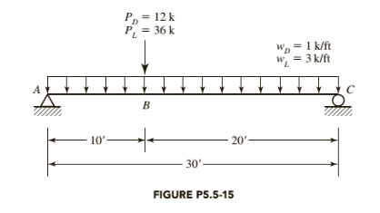
Given:
A992 steel

Formula used:
Calculation:
Determine the nominal flexural strength:
From the
For
This shape is compact because there is no footnote in the dimensions and properties tables to indicate otherwise.
Since
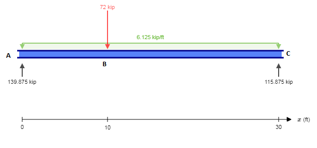
Determine the factored point loads:
D is dead point load and L is live point load
Determine the factored distributed loads:
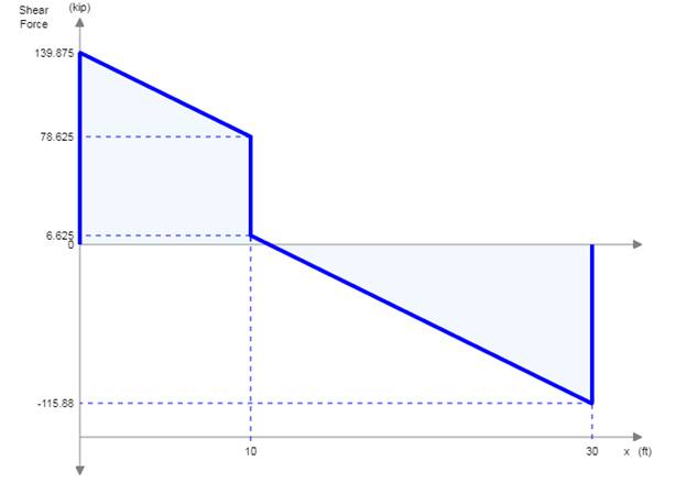
Determine the beam reactions:
Compute Cb :
Since
Conclusion:
(b)
Whether a
Answer to Problem 5.5.15P
Inadequate
Explanation of Solution
Given:
A992 steel
Formula used:
Calculation:
Determine the nominal flexural strength:
From the Zxtable,
For
This shape is compact because there is no footnote in the dimensions and properties tables to indicate otherwise.
Since
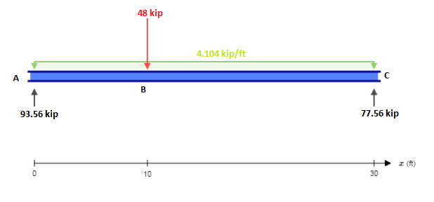
Determine the factored point loads:
Determine the factored distributed loads:
Determine the beam reactions:
Compute Cb :
Since
Conclusion:
Want to see more full solutions like this?
Chapter 5 Solutions
Steel Design (Activate Learning with these NEW titles from Engineering!)

- A rectangular beam has a width b = 300 mm, and effective depth d = 500 mm and a total height h = 550 mm. The beam is reinforced with three bars ᶲ 20 mm. Compute the nominal strength of the beam cross section Mn and the design moment Mu. Use f’c = 35 MPa and Fy= 420 MPa.arrow_forwardCheck the shear strength of an interior beam-column joint. The columns have 20 in. square cross-section, and 12ft clear height. The maximum probable moment strength of columns is (Mpr)ed. 520 ft-kips. The framing beams have the following geometry and reinforcement: Mpr = 345 ft-kips and Mpr = 213 ft-Kips; Top Bar = 5- #8 & Bot. Bar = 3 #8 Additional given data: fe= 4,000 psi; fy=60,000 psiarrow_forwardRead the question carefully and give me right solution according to the question. A W12x79 of A573 Grade 60 (Fy=415 MPa) steel is used as a compression member. It is 8 m long, pinned at the top fixed at the bottom, and has additional support in the weak direction at mid-height. Properties of the section are as follows: A = 14,500 mm^2 Ix = 258.6 x 10^6 mm^4 Iy = 84.375 x 10^6 mm^4 Calculate the effective slenderness ratio with respect to strong axis buckling using theoretical value of k.arrow_forward
- A W 360 x 744 is used as a beam to support a concrete floor system. The floor is to carry atotal load of 250 kPa. The beam is simply supported over a span of 6 m. Assume the beamis laterally supported over its length. Use A36 steel with Fy = 250 MPa. Allowabledeflection is L/360.a. Determine the center to center spacing of the beams without exceeding the allowableshear stress.b. Determine the center to center spacing of the beams without exceeding the allowablebending stress.c. Determine the center to center spacing of the beams without exceeding the allowabledeflection.arrow_forwardFind the allowable safe load P if the stresses in the bar are the following :AB=60 ksi BC =50ksi CD=70ksiarrow_forwarda cantilever beam is 280mm by 500 mmand is reinforced with 4-20mm diameter bars. determine if the 2.50 m long beam is adequate to carry uniform load 15 kn/m and a concentrated load at the cantilever end. Use f'c =21 Mpa, Fy= 275 mpa. Neglect weight of beam. Use n= 9arrow_forward
- A structural steel member is in the form of tee. bf= 300mm , tf= 100mm, bw= 200mm, d=300, fy= 248 Mpa. Determine the following: a. location of plastic neutral axis from the top of the beam b. plastic section modulus c. plastic moment capacityarrow_forwardDesign the beam to resist the loads shown using WSD Method. Take fc = 9 MPa, fs = 124 MPa, n= 11, bar diameter = 20 mm. Take b = d/2arrow_forwardA cantilever of rectangular section is 70 mm wide and 250 mm deep at the fixed end andtapers uniformly to 75 mm wide and 100 deep at the free end. The projecting length is1800 mm, and there is a load of 1800 N at the free end. Calculate the deflection of thefree end and the maximum bending stress. Take E = 14000 N/mm2. The cantilever is madeof timber.arrow_forward
- A column is made of two Channel sections as shown. They are latticed together by light diagonal bracing. The bracing prevents them from moving independently of each other however it does not itself add to the inertia properties. The column is 480" long and is Ball and Socket supported on each end. The column is A36 steel with E = 29,000 ksi. Determine the largest axial compressive load that can be supported with a safety factor of 2.arrow_forwardPLEASE DRAW AND LABEL PROPERLY THE FBD. THANK YOU. Use Cantilever Method. from the frame loaded as shown. Solve the following: a. Axial force at column IE.b. Shear force at girder IJ.c. End moment at girder IJ.d. Axial force at column EA.e. Shear force at girder EF. g. End moment at girder EF.h. Moment at column A.arrow_forwardThe T-beam in the floor system has a slab thickness of 90 mm and supported by beams 6.5 m span. The beam is casts monolithically with the slab. The spacing of beams is 2 m on centers and width the web is 400 mm. The effective depth of the beam is 600 mm. It is reinforced at tension side with 8-28mm Φ bars. fc’ = 28 MPa, fy = 415 MPa 1. Which of the following most nearly give the effective width of the flange? a. 1565 mm b. 1305 mm c. 1275 mm d. 1625 mm 2. Which of the following most nearly gives the depth of compression block? a. 62.25 mm b. 52.86 mm c. 60.26 mm d. 58.29 mm 3. Which of the following gives the nominal moment capacity of the beam? a. 1461.25 kN/m b. 1156.36 kN/m c. 1163.15 kN/m d. 1172.58 kN/marrow_forward
 Steel Design (Activate Learning with these NEW ti...Civil EngineeringISBN:9781337094740Author:Segui, William T.Publisher:Cengage Learning