
(a)
Whether a
Answer to Problem 5.5.14P
Inadequate
Explanation of Solution
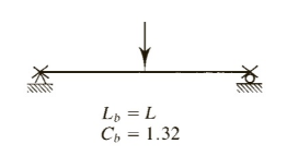
Given:

Formula used:
Lpis unbraced length in an inelastic behavior
Lris unbraced length in an elastic behavior
Mn is nominal moment strength
Mpis plastic moment capacity
Calculation:
All channel shapes in the Manual are compact.(There are no footnotes to indicate otherwise)
For an
A is Cross-sectional area
Sxis Elastic section modulus about X -axis
Zxis Plastic section modulus about X -axis
Iyis Moment of inertia about Y -axis
ryis Radius of gyration about Y -axis
Syis Elastic section modulus about Y -axis
Cwis Warping constant
h0is Distance between centroid of flanges
J is Torsional moment of inertia
For channels,
For
From the below given figure in the textbook,
Conclusion:
(b)
Whether a
Answer to Problem 5.5.14P
Inadequate
Explanation of Solution
Given:
Formula used:
Mn is nominal moment strength
Mpis plastic moment capacity
Calculation:
All channel shapes in the Manual are compact. (There are no footnotes to indicate otherwise)
For an
A is Cross-sectional area
Sxis Elastic section modulus about X -axis
Zxis Plastic section modulus about X -axis
Iyis Moment of inertia about Y -axis
ryis Radius of gyration about Y -axis
Syis Elastic section modulus about Y -axis
Cwis Warping constant
h0is Distance between centroid of flanges
J is Torsional moment of inertia
For channels,
For
From the below given figure in the textbook,

Conclusion:
Want to see more full solutions like this?
Chapter 5 Solutions
Steel Design (Activate Learning with these NEW titles from Engineering!)

- Determine the design moment strengths of the section. fy = 60 ksi and f`c = 4 ksiarrow_forwardA rectangular beam has dimensions of 250 mm width and an effective depth of 430 mm. It is subjected to shear dead load of 102 kN and shear live load of 114 kN. Use f'c = 20.7 MPa and fyt = 276 MPa for 12 mm diameter U-stirrup. Design the required spacing of the shear reinforcement.arrow_forwardColumn ABC has a uniform rectangular cross-section with b = 12 mm and d = 22 mm. The midpoint C of the column is braced so that it cannot move in the y-direction. Using Euler's formula and knowing that a factor of safety of 3.3 is required, determine the largest allowable centric load Pall that can be applied. Use E = 200 GPa, and assume L = 800 mm.arrow_forward
- 2. A square aluminum bar is to support a load of 65kN on a length of 4.50 m. Assume pinned ends, Determine the length of each side E-70 GPa.arrow_forwardQuestion (1): A rectangular beam has a width b = 400 mm, and effective depth d = 850 mm and a total height h = 900 mm. The beam is subjected to an ultimate moment Mu = 1500 kN.m and an ultimate shear force Vu = 700 kN. 1- ) Design the beam for flexure to calculate the required area of steel. 2-) Using stirrups Φ 10 mm ( No.10) diameter, calculate the required spacing (s) between the stirrups at the ultimate shear force section. For all questions, Use f’c= 28 MPa and Fy= 420 MPaarrow_forwardDetermine the elongation of the tapered cylindrical aluminum bar caused bythe 30-kN axial load. Use E = 72 GPa.arrow_forward
- A steel control rod is 5.5 ft long and must not stretch more than 0.04 in. when a 2-kip tensile load is applied toit. Knowing that E = 29 x 106 psi, determine (a) the smallest diameter rod that should be used, (b) thecorresponding normal stress caused by the load.arrow_forwardDoes the column shown below have enough available strength to support the given working loads? Use ASD. Take E = 29.272 ksi, ry = 2.031 in, K = 1, Fy = 59.03 ksi, Ag = 32.79 in2arrow_forwardFor the simple truss shown in the diagram, where the applied vertical downward load PP = 514 N, calculate the load in member AB (in N). Indicate a tensile load as +ve and a compressive load as -ve. Take aa = 2.7 metres.arrow_forward
- A W 360 x 44 of A992 steel column (Fy =345 MPa) having a length of 4m is fixed at both ends. Compute the effective width, be, of the slender web.Compute the value of reduction factor, Q, due to slender elementsin compression members.Compute the nominal compressive strength of the W-section.Properties of W 360 x 44Ag = 5710 mm2d = 351 mmbf = 171 mmtf = 9.78 mm tw = 6.86 mmkdes = 19.9 mmk1 = 19.1 mmrx = 146 mmry = 37.8 mmarrow_forwardThe steel frame (E=200 GPa) shown has a diagonal brace BD with an area of 1920 mm2. Determine thelargest allowable load P if the change in length of member BD is not to exceed 2.5 mmarrow_forwardDesign the beam to resist the loads shown using WSD Method. Take fc = 9 MPa, fs = 124 MPa, n= 11, bar diameter = 20 mm. Take b = d/2arrow_forward
 Steel Design (Activate Learning with these NEW ti...Civil EngineeringISBN:9781337094740Author:Segui, William T.Publisher:Cengage Learning