
(a)
The distance
Answer to Problem 5.2.2P
Explanation of Solution
Given:
An unsymmetrical flexural member consists of a
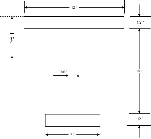
Concept Used:
As the given flexural member is unsymmetrical, therefore, the plastic neutral axis of the section won’t lie on the center of the member.
We will use the concept of equilibrium of forces, to calculate the distance
Calculation:
Now, as we have the following equation
Where,
As the force is equal, we have
Now, calculating the area of the top flange, as follows:
Substituting the values, we have
Calculating the area of the web above the neutral axis, as follows:
Substituting the values, we have
Now, calculating the area of component above the plastic neutral axis as follows:
Now, calculating the area of the bottom flange, we have
Substitute the
Calculating the area of the web below the neutral axis, as follows:
Substituting the values, we have
Calculating the area of the component below the plastic neutral axis as follows:
Now for computing the neutral axis, use
Substitute the values, we have
Conclusion:
Therefore, the distance
(b)
Plastic moment MPfor the horizontal plastic neutral axis.
Answer to Problem 5.2.2P
Explanation of Solution
Given:
An unsymmetrical flexural member consists of a
Calculation:
We have the following formula for the plastic moment of the section
Where,
And we have following formula for calculating the plastic section modulus
We have,
As we have calculated, the distance
We now have the following diagram to consider:
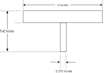
Calculate the area of the top flange as follows:
Now, the area of the web portion that is left is as follows:
Now, calculating the centroidal distance of the web as follows:
Now, calculating the centroidal distance of the top flange as follows:
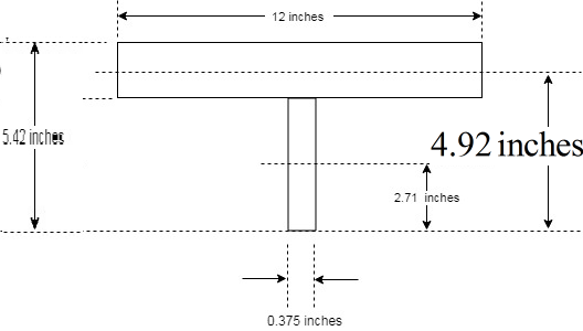
Following figure shows the centroidal distances that were found in the above steps.
Calculating
| Member Component | |||
| Web | |||
| Top Flange | |||
| Total |
Now calculating the value of
Now, similarly find for the lower half section, we have the following figure
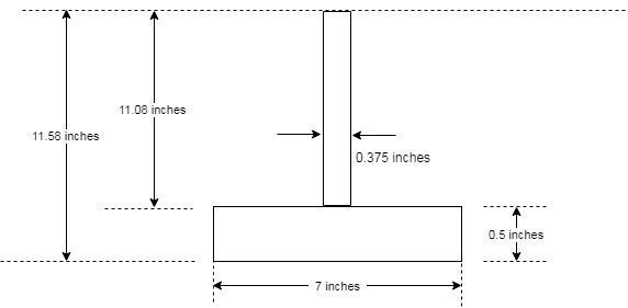
Calculate the area of the bottom flange as follows:
Now, the area of the web portion that is left is as follows:
Now, calculating the centroidal distance of the web as follows:
Now, calculating the centroidal distance of the bottom flange as follows:
Calculating
| Member Component | |||
| Web | |||
| Top Flange | |||
| Total |
Now calculating the value of
Now, calculating the plastic section modulus as follows:
Substituting the values, we have
And
Now, for the plastic moment of the section, we have
Substituting the values
Conclusion:
Therefore, the plastic moment MP for the horizontal plastic neutral axis is
(c)
The plastic section modulus Z with respect to the minor principal axis.
Answer to Problem 5.2.2P
Explanation of Solution
Given:
An unsymmetrical flexural member consists of a
Calculation:
To find thePlastic section modulus Z with respect to the minor principal axis, we need to know that the vertical line or axis is considered to be the minor principal axis, therefore as we know that the member is symmetrical along the y-axis, and the same axis is the minor principal axis which confirms that the plastic neutral axis is passing through its center.
We have the following formula for the plastic section modulus:
Where,
and A is the total area of cross section.
Now, as we know that the plastic neutral axis is passing through the center of the minor principal axis, we conclude
And know we need to find any one of them and let that be equal to
Thus, we have
We can find the
| Member Component | |||
| Top Flange | |||
| Web | |||
| Bottom Flange | |||
| Total |
Calculating the centroidal distance as follows:
Calculation of plastic section modulus is as follows:
Substituting the values, we have
Conclusion:
Therefore, the value of plastic section modulus Z with respect to the minor principal axis is
Want to see more full solutions like this?
Chapter 5 Solutions
Steel Design (Activate Learning with these NEW titles from Engineering!)

- A flexural member is fabricated from two flanges plates 1/2" x 18" and a web plate 5/16" x 20". The yield stress of the steel is 36 ksi. a. Compute the elastic modulus and the yield moment with respect to major principal axis. b. Compute the plastic modulus and the plastic moment with respect to major principal axis.arrow_forwardRigid bar ABCD is loaded and supported as shown. Steel [E = 28400 ksi] bars (1) and (2) are unstressed before the load P is applied. Bar (1) has a cross-sectional area of 0.75 in.2 and bar (2) has a cross-sectional area of 0.45 in.2. After load P is applied, the strain in bar (1) is found to be 850 μεμε. Assume L1=53 in., L2=79 in., a=34 in., b=33 in., and c=30 in. Determine:(a) the stresses in bars (1) and (2).(b) the vertical deflection vD of point D on the rigid bar.(c) the load P.arrow_forwardA W 12 X 35 steel cantilever beam is subjectedto an axial load P =10 kips and a transverse loadV =15 kips. The beam has length L = 6 ft. (a) Calculatethe principal normal stresses and the maximumshear stress for an element located at C near the fixedsupport. Neglect the weight of the beam. (b) Repeat Parta for point D which is 4 in. above point C (see figure).See Table F-1(a), Appendix F, for beam properties.arrow_forward
- A compressive load P is transmitted througha rigid plate to three magnesium-alloy bars that areidentical except that initially the middle bar is slightlyshorter than the other bars (see figure). The dimensionsand properties of the assembly are as follows:length L = 1.0 m, cross-sectional area of each barA = 3000mm2, modulus of elasticity E = 45 GPa,and the gap s = 1.0 mm.(a) Calculate the load P1 required to close the gap.(b) Calculate the downward displacement d of therigid plate when P = 400 kN.(c) Calculate the total strain energy U of the threebars when P = 400 kN.(d) Explain why the strain energy U is not equal toPδ / 2. Hint: Draw a load-displacement diagram.arrow_forwardThe steel tie bar shown in Figure 2 is to be designed to carry a tensile force of magnitude P = 30 kips whenbolted between double brackets at A and B. the bar will be fabricated from 0.5* ? inches thick plate. Forthe grade of steel to be used, the maximum allowable stresses are: Normal stress = σn = 25 ksi, Bearingstress = σb = 55 ksi and Shearing stress = τ = 4.5* ? ksi. Solve for the values of (a) the diameter d of thebolt, (b) the dimension b at each end of the bar and (c) the dimension h of the bar.arrow_forwardA steel bracket of solid circular crosssection is subjected to two loads, each of which isP = 4.5 kN at D (see figure). Let the dimension variablebe b = 240 mm.(a) Find the minimum permissible diameter dminof the bracket if the allowable normal stress is110 MPa.(b) Repeat part (a), including the weight ofthe bracket. The weight density of steel is77.0 kN/m3.arrow_forward
- Read the question carefully. Give me right solution according to the question. Find the load P in KN will make the simply supported beam yield due to bending stress if the yield stress is 250 Mpa. vertical load p is acting at mid-span. beam is made of steel E steel =200000 Mpa Ix=372*10^6 mm4 Y centroid=230 mmarrow_forwardThe axial assembly consists of a solid 1.05-in.-diameter aluminum alloy [E = 9700 ksi, v = 0.29, 12.3 × 10⁻⁶/°F] rod (1) and a solid 1.4-in.-diameter bronze [E = 13300 ksi, v = 0.22, 9 × 10⁻⁶/°F] rod (2). Assume L1=17 in., L2=24 in. If the supports at A and C are rigid and the assembly is stress free at 10°F, determine: (a) the normal stresses , in both rods at 162°F (positive if tensile, negative if compressive). (b) the displacement uB of flange B (positive if to the right, negative to the left). (c) the change in diameter of the aluminum rod.arrow_forward29. Calculate the compressive stress in the brass tube in MPa. A. 7.9B. 8.2C. 9.8D. 10.4arrow_forward
- A hollow steel [E = 30,000 ksi] tube (1) with an outside diameter of 3.00 in. and a wall thickness of 0.223 in. is fastened to a solid 1.75-in.-diameter aluminum [E = 10,000 ksi] rod. The assembly is attached to unyielding supports at the left and right ends and is loaded as shown. Assume P=18 kips, Q=13 kips, L1=4 ft, L2=6 ft, and L3=6 ft. Determine(a) the stresses in all parts of the axial structure.(b) the deflections of joints B and C.arrow_forwardThe dimensions of a rectangular beam are limited to b = 300 mm and h = 770 mm. Assume that the bar centroid of tension bars is 70 mm from the beam edge and that of compression bars is 60 mm. Using f’c = 28 MPa, long bar fy = 415 MPa, calculate the following for a factored bending moment of 1200 kN: a. Maximum steel ratio limiting the tensile strain to 0.004. b. Required amount of tensile reinforcement if the tensile steel strain is limited to 0.005. c. Required amount of compression reinforcement.arrow_forwardA steel beam is bolted to a steel girder by a connection similar to that in the figure shown below. The diameter of the bolt is 10 mm, and the thickness of each angle bar is 4 mm. For each bolt, assume that the allowable bearing stress is 224 MPa. Find the allowable load in kN on the connection. Assume the thickness of the web of the beam to be 7 mm and the thickness of the web of the girder to be 8 mm The final answer should include two decimal placesarrow_forward
 Steel Design (Activate Learning with these NEW ti...Civil EngineeringISBN:9781337094740Author:Segui, William T.Publisher:Cengage Learning