
Concept explainers
(a)
Plastic section modulus
Answer to Problem 5.2.1P
The plastic section modulus
Explanation of Solution
Given:
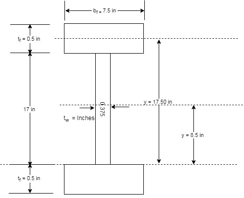
A flexural member is fabricated from two flange plates
Concept used:
The section is a symmetrical section which implies that the plastic neutral axis of the given section is same as the neutral of the given section. Therefore, calculating the lever arm and the centroid of the upper half of the given section, we can find the plastic section modulus.
We have the following figure that will define the terms that we have been given as per the question.

Calculation:
The following is the tabular measurement of every component required:
| Elements | |||||
| Web | |||||
| Flange | |||||
| Sum |
Calculating the centroid of the top half as :
Substitute the values in the above equation.
Now, calculating the moment arm, we have the following formula :
Where, a is the moment arm of the section.
Now, the plastic section modulus can be calculated as follows:
Where, Z is plastic section modulus and A is area.
Calculating the plastic moment as follows:
Substitute the value of
Conclusion:
Therefore, the plastic section modulus
(b)
Elastic section modulus,
Answer to Problem 5.2.1P
The elastic section modulus,
Explanation of Solution
Given:
A flexural member is fabricated from two flange plates
Concept used:
The section is a symmetrical section which implies that the elastic neutral axis of the given section is coinciding with the neutral of the given section. Therefore, calculating the moment of inertia at the major axis using parallel axis theorem, we can find the elastic section modulus.
We have the following figure that will define the terms that we have been given as per the question.
Calculation:
The following is the tabular measurement of every component required:
| Elements | ||||
| Web | ||||
| Top Flange | ||||
| Bottom Flange | ||||
| Sum |
Calculate the Elastic section modulus S with the following formula
Where, C is the distance between the extreme fiber of the section and the neutral axis and is equal to
Here,
By substituting the values in the above equation, we have
Substitute the value of c in the following equation,
Now, calculate the yield moment
Substitute the value of
Conclusion:
Therefore, the elastic section modulus,
Want to see more full solutions like this?
Chapter 5 Solutions
Steel Design (Activate Learning with these NEW titles from Engineering!)


- The beam seciton shown below has moment of inertia about its neutral axis: I = 301.3 (10 -6)m 4 , and if this section is under a bending moment of 22 kN m, please calculate the normal stress at Point B: ____ MPa. Calculate your answer to 1 decimal place.arrow_forwardLoad P is applied to joint D and the temperature increases by 50 °F. There are two steel (E = 29*10^6 psi; a = 6.5*10^-6/°F) AD and DC and a bronze (E = 16*10^6 psi; a = 9*10^-6/°F) BD with a length of 50 inches. Each bar is a 0.75 inch diameter. Find the deformation of every rod, the displacement at D, and the stress in each rod.arrow_forwardA flexural member is fabricated from two flanges plates 1/2" x 18" and a web plate 5/16" x 20". The yield stress of the steel is 36 ksi. a. Compute the elastic modulus and the yield moment with respect to major principal axis. b. Compute the plastic modulus and the plastic moment with respect to major principal axis.arrow_forward
- A frame is built with members ACB and DC to support load P as shown. Member DC has a rectangular cross section with width of 25 mm and thickness t. Stress-strain curve for the material of which the member DC is made is also provided below. a. Determine the thickness t so that member DC does not yield. (You can assume same behavior for compression and tension)b. Determine the diameters of the pin A and D if allowable shear stress for pins is ???? = 40 ???.arrow_forwardA hollow steel [E = 30,000 ksi] tube (1) with an outside diameter of 3.50 in. and a wall thickness of 0.201 in. is fastened to a solid 2.00-in.-diameter aluminum [E = 10,000 ksi] rod. The assembly is attached to unyielding supports at the left and right ends and is loaded as shown. Assume P=19 kips, Q=13 kips, L1=7 ft, L2=9 ft, and L3=9 ft. Determine(a) the stresses in all parts of the axial structure.(b) the deflections of joints B and C.arrow_forwardGiven: -The members are a semi circular cross section with a radius of 16mm -Thickness of each member is 14mm -Diameter of the rivet used is 18mm Determine: a. Cross sectional area of the members b. Internal load in member AB, and indicate if tension or compression c. Internal load of member BD, and indicate if tension or compression d. Normal stress in member AB e. Bearing stress in member BDarrow_forward
- Rigid bar ABCD is loaded and supported as shown. Steel [E = 28400 ksi] bars (1) and (2) are unstressed before the load P is applied. Bar (1) has a cross-sectional area of 0.75 in.2 and bar (2) has a cross-sectional area of 0.45 in.2. After load P is applied, the strain in bar (1) is found to be 850 μεμε. Assume L1=53 in., L2=79 in., a=34 in., b=33 in., and c=30 in. Determine:(a) the stresses in bars (1) and (2).(b) the vertical deflection vD of point D on the rigid bar.(c) the load P.arrow_forwardA solid brass [E = 98 GPa] axial member is loaded and supported as shown. Segments (1) and (2) each have a diameter of 20 mm and segment (3) has a diameter of 15 mm. Assume L1 = 1.8 m, L2 = 1.2 m, L3 = 1.5 m, R = 38 kN, Q = 12 kN, and P = 22 kN. Determine:(a) the deformation of segment (2).(b) the deflection of joint D with respect to the fixed support at A.(c) the maximum normal stress in the entire axial member.arrow_forwardA tripe-U shear mount used four 10 mm x 60 mm x 100 mm hard rubber blocks. Upon loading, the upper U framedeflected by 1.5 mm. The elastic modulus of rubber is 50 MPa. Determine the Poisson’s ratio of the rubber used.Determine the pressure between the rubber and the wall.Determine the Strain of Side KL.arrow_forward
- A cantilever beam AB of length L = 6.5 ft supportsa trapezoidal distributed load of peak intensity q,and minimum intensity q/2, that includes the weight ofthe beam (see figure). The beam is a steel W12 X14wide-flange shape (see Table F-1(a), Appendix F).Calculate the maximum permissible load q basedupon (a) an allowable bending stress σallow =18 ksiand (b) an allowable shear stress τallow = 7.5 ksi.Note: Obtain the moment of inertia and section modulusof the beam from Table F-1(a).arrow_forwardThe rigid bar ABCD of negligible weight is initially horizontal, and the steel rods attached at A and C are stress-free at 0 °F. If the temperature is dropped to -40°F and the 20-kip load is then applied, determine the stress in each steel rod at A and C. Use E = 29x10^6 psi and x = 6.5 x 10^-6/ op for steel.arrow_forwardA T section of a beam is fabricated from 2 - 12 mm x 150 mm steelplates and joined by welding as shown in Figure ST - 904. It carries a live loadof 6.5 kN/m extending half of its span. Neglect the weight 1. Compute the maximum compressive stress. ( bending stress incompression )2. Compute the maximum tensile stress. ( bending stress intension )3. Compute the maximum shear stress. 4. Compute the shear stress between the junction of web and flange. 5. Compute the maximum deflection. EI is constant.arrow_forward
 Steel Design (Activate Learning with these NEW ti...Civil EngineeringISBN:9781337094740Author:Segui, William T.Publisher:Cengage Learning