
ANALYSIS+DESIGN OF LINEAR CIRCUITS(LL)
8th Edition
ISBN: 9781119235385
Author: Thomas
Publisher: WILEY
expand_more
expand_more
format_list_bulleted
Concept explainers
Videos
Textbook Question
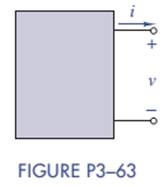
Chapter 3, Problem 3.63P
Assume that Figure P3-63 represents a model of the auxiliary output port of a car. The output current is
Expert Solution & Answer
Want to see the full answer?
Check out a sample textbook solution
Students have asked these similar questions
60 V
D1
D2
2 kohm
D4
D3
-60 V
Assume that an input signal is applied to the circuit given above, as shown in the figure next to
it. Accordingly, answer the following questions. The diodes used are silicon diodes, their
operating voltages are 0.7 volts, and can be omitted because their resistance is very small.
Write the name of this circuit, thinking about which circuit we do in the courses is equivalent to
the purpose.
5 For the following circuit:
a) Draw a table to mention the names, the states (ON/OFF) and turn on voltages for all the diodes of
the circuit. (V = 3.5V for D3) and draw the equivalent circuit.
b) Find the voltage across R1, R2, R3
c) Find the current through D1 , Dz , D3 and D4
D1
Si
R2
D2
5002
Si
R1
7502
R3
D3
D4
V1
1kn
Blue
GaAs
10v
60 V
D1
D2
2 kohm
DA
D3
-60 V
Assume that an input signal is applied to the circuit given above, as shown in the figure next to
it. Accordingly, answer the following questions. The diodes used are silicon diodes, their
operating voltages are 0.7 volts, and can be omitted because their resistance is very small.
Calculate V p-out( Vm ) for this circuit.
Chapter 3 Solutions
ANALYSIS+DESIGN OF LINEAR CIRCUITS(LL)
Ch. 3 - Formulate node-voltage equations for the circuit...Ch. 3 - (a) Formulate node-voltage equations for the...Ch. 3 - (a) Formulate node-voltage equations for the...Ch. 3 - Formulate node-voltage equations for the circuit...Ch. 3 - (a) Formulate node-voltage equations for the...Ch. 3 - Choose a ground wisely and formulate node-voltage...Ch. 3 - The following are a set of node-voltage equations;...Ch. 3 - Choose a ground wisely and formulate node-voltage...Ch. 3 - Formulate node-voltage equations for the circuit...Ch. 3 - Formulate node-voltage equations for the circuit...
Ch. 3 - (a) Formulate mesh-current equations for the...Ch. 3 - (a) Formulate mesh-current equations for the...Ch. 3 - (a) Formulate mesh-current equations for the...Ch. 3 - Prob. 3.16PCh. 3 - Formulate mesh-current equations for the circuit...Ch. 3 - For the circuit of figure P3-19 solve for iA,iB,...Ch. 3 - Formulate mesh-current equations for the circuit...Ch. 3 - The circuit in Figure P3-21 seems to require two...Ch. 3 - Formulate mesh-current equations for the circuit...Ch. 3 - Use simple engineering intuition to find the input...Ch. 3 - In Figure P3-24 all of the resistors are 1k and...Ch. 3 - Use Figure P3-24 and MATLAB to solve the following...Ch. 3 - Formulate mesh-current equations for the circuit...Ch. 3 - Find vO for the block diagram shown in figure...Ch. 3 - Design a voltage-divider circuit that will realize...Ch. 3 - Design a current-divider circuit that will realize...Ch. 3 - Using a single resistor, design a circuit that...Ch. 3 - Find the proportionality constant K=vO/vS for the...Ch. 3 - Find the proportionality constant K=iO/vS for the...Ch. 3 - Find the proportionality constant K=vO/iS for the...Ch. 3 - Find the proportionality constant K=iO/iS for the...Ch. 3 - Find the proportionality constant K=vO/vS for the...Ch. 3 - Use the unit output method to find K and vO in...Ch. 3 - Use the unit output method to find K and vO in...Ch. 3 - Use the unit output method to find K in Figure...Ch. 3 - Use the superposition principle to find vO in...Ch. 3 - Use the superposition principle to find vO in...Ch. 3 - Use the superposition principle to find vO in...Ch. 3 - (a) Use the superposition principle to find vO in...Ch. 3 - A linear circuit containing two sources drives a...Ch. 3 - A block diagram of a linear circuit is shown in...Ch. 3 - A certain linear circuit has four input voltages...Ch. 3 - When the current source is turned off in the...Ch. 3 - For the circuit in Figure P3—51, find the Thévenin...Ch. 3 - For the circuit in Figure P3—52, find the Thévenin...Ch. 3 - For the circuit of Figure P3—53, find the Thévenin...Ch. 3 - Find the Thévenin or Norton equivalent circuit...Ch. 3 - Find the Thévenin or Norton equivalent circuit...Ch. 3 - Find the Thévenin equivalent circuit seen by RL in...Ch. 3 - Find the Norton equivalent seen by RL in Figure...Ch. 3 - You need to determine the Thévenin equivalent...Ch. 3 - Find the Thévenin equivalent seen by RL in figure...Ch. 3 - The purpose of this problem is to use Thévenin...Ch. 3 - The circuit in Figure P3-62 was solved earlier...Ch. 3 - Assume that Figure P3-63 represents a model of the...Ch. 3 - The iv characteristic of the active circuit...Ch. 3 - You have successfully completed the first course...Ch. 3 - The Thévenin equivalent parameters of a practical...Ch. 3 - Use a sequence of source transformations to find...Ch. 3 - The circuit in Figure P3-68 provides power to a...Ch. 3 - A nonlinear resistor is connected across a...Ch. 3 - Prob. 3.71PCh. 3 - Find the Norton equivalent seen by RL in Figure...Ch. 3 - Find the Thévenin equivalent seen by RL in Figure...Ch. 3 - Find the Thévenin equivalent seen by RL in Figure...Ch. 3 - For the circuit of Figure P3-75, find the value of...Ch. 3 - For the circuit of Figure P3-76, find the value of...Ch. 3 - The resistance R in Figure P3-77 is adjusted until...Ch. 3 - When a 5-k resistor is connected across a...Ch. 3 - Find the value of R in the circuit of Figure P3-79...Ch. 3 - For the circuit of Figure P3-80, find the value of...Ch. 3 - A 1-k load needs 10 mA to operate correctly....Ch. 3 - A practical source delivers 25 mA to a load. The...Ch. 3 - A 10-V source is shown in Figure P3-83 that is...Ch. 3 - (a)Select RL and design an interface circuit for...Ch. 3 - The source in Figure P3-85 has a 100-mA output...Ch. 3 - Figure P3-86 shows an interface circuit connecting...Ch. 3 - Prob. 3.87PCh. 3 - In this problem, you will design two interface...Ch. 3 - Two teams are competing to design the interface...Ch. 3 - The bridge-T attenuation pad shown in FigureP3-90...Ch. 3 - Design two interface circuits in Figure P3-91 so...Ch. 3 - Design the interface circuit in Figure P3-91 so...Ch. 3 - Design the interface circuit in Figure P3-93 so...Ch. 3 - It is claimed that both interface circuits in...Ch. 3 - Audio Speaker Resistance-Matching Network A...Ch. 3 - Interface Circuit Design Using no more than three...Ch. 3 - Battery Design A satellite requires a battery with...Ch. 3 - Design Interface Competition The output of a...Ch. 3 - Prob. 3.106IP
Knowledge Booster


Learn more about
Need a deep-dive on the concept behind this application? Look no further. Learn more about this topic, electrical-engineering and related others by exploring similar questions and additional content below.Similar questions
- 60 V D1 D2 2 kohm D4 D3 -60 V Assume that an input signal is applied to the circuit given above, as shown in the figure next to it. Accordingly, answer the following questions. The diodes used are silicon diodes, their operating voltages are 0.7 volts, and can be omitted because their resistance is very small. What are the diodes/diodes that are active in a positive half-loop? Please type.arrow_forwardA ammeter has a resistance of 0.1 ohm and full range is 100 A. To incraese range to 1000 A find value of shunt resistance. Please solve it.arrow_forwardBased on electric circuit shown in Figure 2. Determine whether the LED 1 and LED 2 is “ON" or "OFF" for V1 = 2V and V1 = 3.5V if for both LEDS are silicon LED. Explain the answer given. V1 OUT R1 OPAMP 100kN V2 LED 1 LED 2 4Vdc R2 500kn Figure 2: Op-Amp circuit with LEDarrow_forward
- Find the Total current flowing through D1 and D2 and D3. Vs= 10v, R1=R2=R3=10kNThe three diodes are silicon. IS ov R1 D2 R2 D3 SI R4 10k R3arrow_forward4 1.0 k VS2 VSI 25 V 8 V Diodes D1 and D2 in the figure are assumed ideal, what is the current through the diodes? * D₁ B R www Carrow_forwardDetermine the current through D2. Use practical diode model. Q +10 V 1k2 R1 DI A B D2 D3 R2 R3 Ik2 6-10 V 6 - 20 Varrow_forward
- In the circuit shown in Figure 3-63 (p. 150), find VCE when IC = 1.5 mA. Also, what value of b is required in order for IC to be equal to 1.5mA? Also, what are the values of VE, VB, and VC?arrow_forward10 K D3 The diodes in the circuit are Silicon with forward voltage of 0.7 V. Fill up the table showing the state, voltage and current of each of the diodes. 8 K Show how you validated the state of each diode. Follow the reference shown in determining whether the diode voltages and currents are positive or negative. 5 V 1K 1Di mA Diode State VD + VD - D1 D2 D3arrow_forwardIn the circuit in the figure, D1 diode is made of silicon D2 diode and germanium. Calculate the induced voltage above a 3 kiloohm resistor?arrow_forward
- use the constant voltage drop model in analyzing the diode circuit below: 10 92 V₁ (+ M 1 V D₁ If V₁ is -3 V, what would be the state of the diodes? A. D₁ and D₂ are both OFF C B. D₁ is OFF and D₂ is ON - 1 V D₂ C. D₁ is ON and D₂ is OFF D. D₁ and D₂ are both ON + 1092 Voarrow_forwardSubject: Electronics Engineering To study V-I characteristics of the semiconductor diode and determine D.C & A.C resistance. Write in your own language what you learn from this experimentarrow_forwardQUESTION 2 a) The series-parallel diode circuit in Figure Q2a consists of two diodes made of silicon and germanium. The threshold voltage for silicon diode is 0.7 V and germanium diode is = 0.3 V. Solve for the current I, V, and V2. R1 V1 Si V2 +5 V 4.7 kN R2 10 kN Ge 6 -5 V Figure Q2aarrow_forward
arrow_back_ios
SEE MORE QUESTIONS
arrow_forward_ios
Recommended textbooks for you
 Introductory Circuit Analysis (13th Edition)Electrical EngineeringISBN:9780133923605Author:Robert L. BoylestadPublisher:PEARSON
 Delmar's Standard Textbook Of ElectricityElectrical EngineeringISBN:9781337900348Author:Stephen L. HermanPublisher:Cengage Learning
 Programmable Logic ControllersElectrical EngineeringISBN:9780073373843Author:Frank D. PetruzellaPublisher:McGraw-Hill Education
 Fundamentals of Electric CircuitsElectrical EngineeringISBN:9780078028229Author:Charles K Alexander, Matthew SadikuPublisher:McGraw-Hill Education
 Electric Circuits. (11th Edition)Electrical EngineeringISBN:9780134746968Author:James W. Nilsson, Susan RiedelPublisher:PEARSON
 Engineering ElectromagneticsElectrical EngineeringISBN:9780078028151Author:Hayt, William H. (william Hart), Jr, BUCK, John A.Publisher:Mcgraw-hill Education,
Introductory Circuit Analysis (13th Edition)
Electrical Engineering
ISBN:9780133923605
Author:Robert L. Boylestad
Publisher:PEARSON
Delmar's Standard Textbook Of Electricity
Electrical Engineering
ISBN:9781337900348
Author:Stephen L. Herman
Publisher:Cengage Learning
Programmable Logic Controllers
Electrical Engineering
ISBN:9780073373843
Author:Frank D. Petruzella
Publisher:McGraw-Hill Education
Fundamentals of Electric Circuits
Electrical Engineering
ISBN:9780078028229
Author:Charles K Alexander, Matthew Sadiku
Publisher:McGraw-Hill Education
Electric Circuits. (11th Edition)
Electrical Engineering
ISBN:9780134746968
Author:James W. Nilsson, Susan Riedel
Publisher:PEARSON
Engineering Electromagnetics
Electrical Engineering
ISBN:9780078028151
Author:Hayt, William H. (william Hart), Jr, BUCK, John A.
Publisher:Mcgraw-hill Education,
Latches and Flip-Flops 1 - The SR Latch; Author: Computer Science;https://www.youtube.com/watch?v=-aQH0ybMd3U;License: Standard Youtube License