
ANALYSIS+DESIGN OF LINEAR CIRCUITS(LL)
8th Edition
ISBN: 9781119235385
Author: Thomas
Publisher: WILEY
expand_more
expand_more
format_list_bulleted
Concept explainers
Videos
Textbook Question
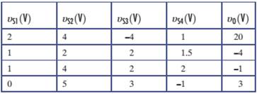
Chapter 3, Problem 3.49P
A certain linear circuit has four input voltages and one output voltage
Expert Solution & Answer
Want to see the full answer?
Check out a sample textbook solution
Students have asked these similar questions
Develop a circuit that will provide an output voltage that is -4 Vm if the input voltage is
Vmsinwt
Problem 4: Given the circuit below, determine the value of V2 so the output waveform is always positive. Explain how this circuit works.
V1
8Vpk
2kHz
0.⁰
V2
40
4.7kQ
D1
Vout
Question 3: Breadboard connections of a circuit are given in the figure below.
1- 2- GND
....
...... ......
0.1µF
10mH
10mH
1kn
a) Draw the schematic diagram of the circuit.
b) Since we can observe the input signal with Channel 1 and the output signal with Channel
2, what does this circuit do? Write the type and purpose of the circuit.
c) Plot the frequency versus transfer function by calculating the required frequencies.
Channel 1+
Function generator
Channel 2+
Chapter 3 Solutions
ANALYSIS+DESIGN OF LINEAR CIRCUITS(LL)
Ch. 3 - Formulate node-voltage equations for the circuit...Ch. 3 - (a) Formulate node-voltage equations for the...Ch. 3 - (a) Formulate node-voltage equations for the...Ch. 3 - Formulate node-voltage equations for the circuit...Ch. 3 - (a) Formulate node-voltage equations for the...Ch. 3 - Choose a ground wisely and formulate node-voltage...Ch. 3 - The following are a set of node-voltage equations;...Ch. 3 - Choose a ground wisely and formulate node-voltage...Ch. 3 - Formulate node-voltage equations for the circuit...Ch. 3 - Formulate node-voltage equations for the circuit...
Ch. 3 - (a) Formulate mesh-current equations for the...Ch. 3 - (a) Formulate mesh-current equations for the...Ch. 3 - (a) Formulate mesh-current equations for the...Ch. 3 - Prob. 3.16PCh. 3 - Formulate mesh-current equations for the circuit...Ch. 3 - For the circuit of figure P3-19 solve for iA,iB,...Ch. 3 - Formulate mesh-current equations for the circuit...Ch. 3 - The circuit in Figure P3-21 seems to require two...Ch. 3 - Formulate mesh-current equations for the circuit...Ch. 3 - Use simple engineering intuition to find the input...Ch. 3 - In Figure P3-24 all of the resistors are 1k and...Ch. 3 - Use Figure P3-24 and MATLAB to solve the following...Ch. 3 - Formulate mesh-current equations for the circuit...Ch. 3 - Find vO for the block diagram shown in figure...Ch. 3 - Design a voltage-divider circuit that will realize...Ch. 3 - Design a current-divider circuit that will realize...Ch. 3 - Using a single resistor, design a circuit that...Ch. 3 - Find the proportionality constant K=vO/vS for the...Ch. 3 - Find the proportionality constant K=iO/vS for the...Ch. 3 - Find the proportionality constant K=vO/iS for the...Ch. 3 - Find the proportionality constant K=iO/iS for the...Ch. 3 - Find the proportionality constant K=vO/vS for the...Ch. 3 - Use the unit output method to find K and vO in...Ch. 3 - Use the unit output method to find K and vO in...Ch. 3 - Use the unit output method to find K in Figure...Ch. 3 - Use the superposition principle to find vO in...Ch. 3 - Use the superposition principle to find vO in...Ch. 3 - Use the superposition principle to find vO in...Ch. 3 - (a) Use the superposition principle to find vO in...Ch. 3 - A linear circuit containing two sources drives a...Ch. 3 - A block diagram of a linear circuit is shown in...Ch. 3 - A certain linear circuit has four input voltages...Ch. 3 - When the current source is turned off in the...Ch. 3 - For the circuit in Figure P3—51, find the Thévenin...Ch. 3 - For the circuit in Figure P3—52, find the Thévenin...Ch. 3 - For the circuit of Figure P3—53, find the Thévenin...Ch. 3 - Find the Thévenin or Norton equivalent circuit...Ch. 3 - Find the Thévenin or Norton equivalent circuit...Ch. 3 - Find the Thévenin equivalent circuit seen by RL in...Ch. 3 - Find the Norton equivalent seen by RL in Figure...Ch. 3 - You need to determine the Thévenin equivalent...Ch. 3 - Find the Thévenin equivalent seen by RL in figure...Ch. 3 - The purpose of this problem is to use Thévenin...Ch. 3 - The circuit in Figure P3-62 was solved earlier...Ch. 3 - Assume that Figure P3-63 represents a model of the...Ch. 3 - The iv characteristic of the active circuit...Ch. 3 - You have successfully completed the first course...Ch. 3 - The Thévenin equivalent parameters of a practical...Ch. 3 - Use a sequence of source transformations to find...Ch. 3 - The circuit in Figure P3-68 provides power to a...Ch. 3 - A nonlinear resistor is connected across a...Ch. 3 - Prob. 3.71PCh. 3 - Find the Norton equivalent seen by RL in Figure...Ch. 3 - Find the Thévenin equivalent seen by RL in Figure...Ch. 3 - Find the Thévenin equivalent seen by RL in Figure...Ch. 3 - For the circuit of Figure P3-75, find the value of...Ch. 3 - For the circuit of Figure P3-76, find the value of...Ch. 3 - The resistance R in Figure P3-77 is adjusted until...Ch. 3 - When a 5-k resistor is connected across a...Ch. 3 - Find the value of R in the circuit of Figure P3-79...Ch. 3 - For the circuit of Figure P3-80, find the value of...Ch. 3 - A 1-k load needs 10 mA to operate correctly....Ch. 3 - A practical source delivers 25 mA to a load. The...Ch. 3 - A 10-V source is shown in Figure P3-83 that is...Ch. 3 - (a)Select RL and design an interface circuit for...Ch. 3 - The source in Figure P3-85 has a 100-mA output...Ch. 3 - Figure P3-86 shows an interface circuit connecting...Ch. 3 - Prob. 3.87PCh. 3 - In this problem, you will design two interface...Ch. 3 - Two teams are competing to design the interface...Ch. 3 - The bridge-T attenuation pad shown in FigureP3-90...Ch. 3 - Design two interface circuits in Figure P3-91 so...Ch. 3 - Design the interface circuit in Figure P3-91 so...Ch. 3 - Design the interface circuit in Figure P3-93 so...Ch. 3 - It is claimed that both interface circuits in...Ch. 3 - Audio Speaker Resistance-Matching Network A...Ch. 3 - Interface Circuit Design Using no more than three...Ch. 3 - Battery Design A satellite requires a battery with...Ch. 3 - Design Interface Competition The output of a...Ch. 3 - Prob. 3.106IP
Knowledge Booster


Learn more about
Need a deep-dive on the concept behind this application? Look no further. Learn more about this topic, electrical-engineering and related others by exploring similar questions and additional content below.Similar questions
- Draw and label a voltage divider that generates0.5V from an input of 1.5V. Then draw and label a current divider that generates 1.25A from an input of1.0A. Pleaseclearlydefine/label the value of all variables (e.g. resistances). If a solution does not exist, then simply state so.arrow_forwardHELP a:Write the equation Vo according to the block diagram given below. b: Design the circuit that will perform the operation by using 0.5 V and 10 V direct current (DC) sources with a single OPAMP.arrow_forwardYou were tasked with modifying an audio amplifier circuit. Amplifier circuits are responsible for increasing the current sent to the speakers, avoiding damaging the sound device. The original design is shown in the figure. You want to increase the current I1 by a factor of 10 (10 times). The conditions of the design area are: Both font values must be increased. None of the values can be equal to 0. What are the new values that you propose for the design of the amplifier? ** Argue your answer by analyzing the results obtained through calculations. (Check image 4 for the circuit)arrow_forward
- V1 R1 V2 Da Db R2 www V3 Given that R1=2k, R2=1k, and Da and Db are Si Diodes: a. What is V3 in terms of V1 when Da is ON? b. What is V3 in terms of V1 when Db is ON? c. What is V3 in terms of V1 when Da and Db is OFF?arrow_forwardR2 741 DI R1 D2 In the circuit on the side, the input signal with a peak value of 4 V is applied case; Plot the graphs V0 (t) and V0 - Vi explaining. specify required values)arrow_forward1. Sketch the Vout and the currents for the given circuits shown below when a step input is applied at the input. Clearly mention all possibilities. R₁ C₁ Vout 1/₂ R₂ C₁ Vin R C h R₁ C₁ → b R₂ G₁ Voutarrow_forward
- Please answer all subpart please Asap for like this please all subpart...arrow_forwardReset WED W=O W =l EhD DII W=0 Derive the following state-table Present state Next state output z2zlz0 W=0 W=1 A 000 B 001 C 010 D 011 E 100arrow_forwardHello, I am very confused what is a hyrbrid pi model. Can you please make a hypbrid pi model from this circuit and explain thank you I will likearrow_forward
- V- Design an ADC circuit using OPAMParrow_forwardDesign an op-amp circuit that can perform this operation: v0=2v1v2-3v3arrow_forwardThe Junction Gate Field Effect Transistor is one of the simplest types of field-effect transistor. It is a three-terminal semiconductor device .One of its function is, it serve as an amplifier. As an Engineer you are to design a single stage JFET Amplifier. Explain in your own words this circuit operates, identifying each component in your design circuit and state their functionsarrow_forward
arrow_back_ios
SEE MORE QUESTIONS
arrow_forward_ios
Recommended textbooks for you
 Introductory Circuit Analysis (13th Edition)Electrical EngineeringISBN:9780133923605Author:Robert L. BoylestadPublisher:PEARSON
 Delmar's Standard Textbook Of ElectricityElectrical EngineeringISBN:9781337900348Author:Stephen L. HermanPublisher:Cengage Learning
 Programmable Logic ControllersElectrical EngineeringISBN:9780073373843Author:Frank D. PetruzellaPublisher:McGraw-Hill Education
 Fundamentals of Electric CircuitsElectrical EngineeringISBN:9780078028229Author:Charles K Alexander, Matthew SadikuPublisher:McGraw-Hill Education
 Electric Circuits. (11th Edition)Electrical EngineeringISBN:9780134746968Author:James W. Nilsson, Susan RiedelPublisher:PEARSON
 Engineering ElectromagneticsElectrical EngineeringISBN:9780078028151Author:Hayt, William H. (william Hart), Jr, BUCK, John A.Publisher:Mcgraw-hill Education,
Introductory Circuit Analysis (13th Edition)
Electrical Engineering
ISBN:9780133923605
Author:Robert L. Boylestad
Publisher:PEARSON
Delmar's Standard Textbook Of Electricity
Electrical Engineering
ISBN:9781337900348
Author:Stephen L. Herman
Publisher:Cengage Learning
Programmable Logic Controllers
Electrical Engineering
ISBN:9780073373843
Author:Frank D. Petruzella
Publisher:McGraw-Hill Education
Fundamentals of Electric Circuits
Electrical Engineering
ISBN:9780078028229
Author:Charles K Alexander, Matthew Sadiku
Publisher:McGraw-Hill Education
Electric Circuits. (11th Edition)
Electrical Engineering
ISBN:9780134746968
Author:James W. Nilsson, Susan Riedel
Publisher:PEARSON
Engineering Electromagnetics
Electrical Engineering
ISBN:9780078028151
Author:Hayt, William H. (william Hart), Jr, BUCK, John A.
Publisher:Mcgraw-hill Education,
Current Divider Rule; Author: Neso Academy;https://www.youtube.com/watch?v=hRU1mKWUehY;License: Standard YouTube License, CC-BY