
Videos
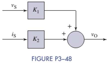
A block diagram of a linear circuit is shown in Figure P3-48. When
Want to see the full answer?
Check out a sample textbook solution
Chapter 3 Solutions
ANALYSIS+DESIGN OF LINEAR CIRCUITS(LL)


- For this DC circuit in MULTISIM. What is the voltage across each resistor, current through each resistor and the DC power dissipated by each resistor. perform in Multisimarrow_forward%3D For the following circuit, calculate the current through R5 and the voltage drop across R5. Use the following parameters for the circuit: Vs = 8 V, R1 = 48, R2 = 8, R2 = 4, R4 = 5, R5 = 20. Rz R3 R5 R4arrow_forwardFind the voltage at node P in the following figure V1 4V 9V b) 8V c) 10V d) 11V O a. 8 O b. 9 Oc. 11 O d. 10arrow_forward
- The parallel combination of R2 and C2 in the circuit shown represents the input circuit to a cathode-ray oscilloscope (CRO). The parallel combination of R1 and C1 is a circuit model of a compensating lead that is used to connect the CRO to the source. There is no energy stored in C1 or C2 at the time when the 10 V source is connected to the CRO via the compensating lead. The circuit values are C1=4 pF, C2=16 pF, R1=1.25 MΩ, and R2=5 MΩ. 1. a) Find vo. 2. b) Find io. 3. c) Repeat (a) and (b) given C1 is changed to 64 pF.arrow_forwardElectrical Engineering How do I create a circuit that does the following. The output voltage Vout is at OV originally. If the input voltage Vin changes from OV to 1V, the Vout should also goes to 1V an will keep as 1V no matter how Vin changes later on. plz help draw the circuit diagram!arrow_forwardSolve for the circuits unknowns in the picture belowarrow_forward
- 500mA 200mA Solve for the value of R3 as shown in the figure. 100mA 50mA "RI 250 13: R2 R3 R4 12arrow_forwardcan you help me find a solution for future problems on how to solve in the future. Need to find the values of R3 and RT and find the total voltage.arrow_forwardidentify the minterms that corresponds to the f and d below. Please be sure you know how to solve correctly and show work. I will also provide an image that states what the answer is without showing work I need to see work and explained how to get there. f=b'c'd' + abd' + abd d=a'c'd + b'cd'arrow_forward
- Construct the DC circuit in MULTISIM. What is the voltage across each resistor, current through each resistor and the DC power dissipated by each resistorarrow_forwardEach of the cells shown in the figure has an emf of 1.50 V and a 0.0750-ohm internalresistance. Find I1, I2, and I3.arrow_forwardQ3. Draw the output voltage waveform for each circuit including the voltage values. (Ideal model) 2.2kQ +30 V -30 V +5 V +50V 0. 47 (1 3.3 k -5 V -50V 2:1 +100V-- IN4001 Ov 10 kn -100V IN4001 00000arrow_forward
 Introductory Circuit Analysis (13th Edition)Electrical EngineeringISBN:9780133923605Author:Robert L. BoylestadPublisher:PEARSON
 Delmar's Standard Textbook Of ElectricityElectrical EngineeringISBN:9781337900348Author:Stephen L. HermanPublisher:Cengage Learning
 Programmable Logic ControllersElectrical EngineeringISBN:9780073373843Author:Frank D. PetruzellaPublisher:McGraw-Hill Education
 Fundamentals of Electric CircuitsElectrical EngineeringISBN:9780078028229Author:Charles K Alexander, Matthew SadikuPublisher:McGraw-Hill Education
 Electric Circuits. (11th Edition)Electrical EngineeringISBN:9780134746968Author:James W. Nilsson, Susan RiedelPublisher:PEARSON
 Engineering ElectromagneticsElectrical EngineeringISBN:9780078028151Author:Hayt, William H. (william Hart), Jr, BUCK, John A.Publisher:Mcgraw-hill Education,