
ANALYSIS+DESIGN OF LINEAR CIRCUITS(LL)
8th Edition
ISBN: 9781119235385
Author: Thomas
Publisher: WILEY
expand_more
expand_more
format_list_bulleted
Concept explainers
Videos
Textbook Question
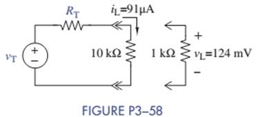
Chapter 3, Problem 3.58P
You need to determine the Thévenin equivalent circuit of a more complex linear circuit. A technician tells you she made two measurements using her DMM. The first was with a
Expert Solution & Answer
Want to see the full answer?
Check out a sample textbook solution
Students have asked these similar questions
3-26 Find the proportionality constant K = io/vo for the circuit in Figure P3-26.
FIGURE P3–26
VS
500 Ω
Μ
1 ΚΩ
Μ
ΣικΩ
iot
Calculate values of asked physical quantities of the circuit:
The circuits terminal voltage is 16.7V and then resistors A&B are in parallel. The resistance of resistor A, is 6.2 ohm and for B it's 7.9 ohm. What's the current going through each resistor?
3-57 For the circuit of Figure P3-57, find the value of RL that
will result in
(a) Maximum voltage. What is that voltage?
(b) Maximum current. What is that current?
(c) Maximum power. What is that power?
10 mA
7kQ
ww
3 ΚΩ
FIGURE P3-57
RL
Chapter 3 Solutions
ANALYSIS+DESIGN OF LINEAR CIRCUITS(LL)
Ch. 3 - Formulate node-voltage equations for the circuit...Ch. 3 - (a) Formulate node-voltage equations for the...Ch. 3 - (a) Formulate node-voltage equations for the...Ch. 3 - Formulate node-voltage equations for the circuit...Ch. 3 - (a) Formulate node-voltage equations for the...Ch. 3 - Choose a ground wisely and formulate node-voltage...Ch. 3 - The following are a set of node-voltage equations;...Ch. 3 - Choose a ground wisely and formulate node-voltage...Ch. 3 - Formulate node-voltage equations for the circuit...Ch. 3 - Formulate node-voltage equations for the circuit...
Ch. 3 - (a) Formulate mesh-current equations for the...Ch. 3 - (a) Formulate mesh-current equations for the...Ch. 3 - (a) Formulate mesh-current equations for the...Ch. 3 - Prob. 3.16PCh. 3 - Formulate mesh-current equations for the circuit...Ch. 3 - For the circuit of figure P3-19 solve for iA,iB,...Ch. 3 - Formulate mesh-current equations for the circuit...Ch. 3 - The circuit in Figure P3-21 seems to require two...Ch. 3 - Formulate mesh-current equations for the circuit...Ch. 3 - Use simple engineering intuition to find the input...Ch. 3 - In Figure P3-24 all of the resistors are 1k and...Ch. 3 - Use Figure P3-24 and MATLAB to solve the following...Ch. 3 - Formulate mesh-current equations for the circuit...Ch. 3 - Find vO for the block diagram shown in figure...Ch. 3 - Design a voltage-divider circuit that will realize...Ch. 3 - Design a current-divider circuit that will realize...Ch. 3 - Using a single resistor, design a circuit that...Ch. 3 - Find the proportionality constant K=vO/vS for the...Ch. 3 - Find the proportionality constant K=iO/vS for the...Ch. 3 - Find the proportionality constant K=vO/iS for the...Ch. 3 - Find the proportionality constant K=iO/iS for the...Ch. 3 - Find the proportionality constant K=vO/vS for the...Ch. 3 - Use the unit output method to find K and vO in...Ch. 3 - Use the unit output method to find K and vO in...Ch. 3 - Use the unit output method to find K in Figure...Ch. 3 - Use the superposition principle to find vO in...Ch. 3 - Use the superposition principle to find vO in...Ch. 3 - Use the superposition principle to find vO in...Ch. 3 - (a) Use the superposition principle to find vO in...Ch. 3 - A linear circuit containing two sources drives a...Ch. 3 - A block diagram of a linear circuit is shown in...Ch. 3 - A certain linear circuit has four input voltages...Ch. 3 - When the current source is turned off in the...Ch. 3 - For the circuit in Figure P3—51, find the Thévenin...Ch. 3 - For the circuit in Figure P3—52, find the Thévenin...Ch. 3 - For the circuit of Figure P3—53, find the Thévenin...Ch. 3 - Find the Thévenin or Norton equivalent circuit...Ch. 3 - Find the Thévenin or Norton equivalent circuit...Ch. 3 - Find the Thévenin equivalent circuit seen by RL in...Ch. 3 - Find the Norton equivalent seen by RL in Figure...Ch. 3 - You need to determine the Thévenin equivalent...Ch. 3 - Find the Thévenin equivalent seen by RL in figure...Ch. 3 - The purpose of this problem is to use Thévenin...Ch. 3 - The circuit in Figure P3-62 was solved earlier...Ch. 3 - Assume that Figure P3-63 represents a model of the...Ch. 3 - The iv characteristic of the active circuit...Ch. 3 - You have successfully completed the first course...Ch. 3 - The Thévenin equivalent parameters of a practical...Ch. 3 - Use a sequence of source transformations to find...Ch. 3 - The circuit in Figure P3-68 provides power to a...Ch. 3 - A nonlinear resistor is connected across a...Ch. 3 - Prob. 3.71PCh. 3 - Find the Norton equivalent seen by RL in Figure...Ch. 3 - Find the Thévenin equivalent seen by RL in Figure...Ch. 3 - Find the Thévenin equivalent seen by RL in Figure...Ch. 3 - For the circuit of Figure P3-75, find the value of...Ch. 3 - For the circuit of Figure P3-76, find the value of...Ch. 3 - The resistance R in Figure P3-77 is adjusted until...Ch. 3 - When a 5-k resistor is connected across a...Ch. 3 - Find the value of R in the circuit of Figure P3-79...Ch. 3 - For the circuit of Figure P3-80, find the value of...Ch. 3 - A 1-k load needs 10 mA to operate correctly....Ch. 3 - A practical source delivers 25 mA to a load. The...Ch. 3 - A 10-V source is shown in Figure P3-83 that is...Ch. 3 - (a)Select RL and design an interface circuit for...Ch. 3 - The source in Figure P3-85 has a 100-mA output...Ch. 3 - Figure P3-86 shows an interface circuit connecting...Ch. 3 - Prob. 3.87PCh. 3 - In this problem, you will design two interface...Ch. 3 - Two teams are competing to design the interface...Ch. 3 - The bridge-T attenuation pad shown in FigureP3-90...Ch. 3 - Design two interface circuits in Figure P3-91 so...Ch. 3 - Design the interface circuit in Figure P3-91 so...Ch. 3 - Design the interface circuit in Figure P3-93 so...Ch. 3 - It is claimed that both interface circuits in...Ch. 3 - Audio Speaker Resistance-Matching Network A...Ch. 3 - Interface Circuit Design Using no more than three...Ch. 3 - Battery Design A satellite requires a battery with...Ch. 3 - Design Interface Competition The output of a...Ch. 3 - Prob. 3.106IP
Knowledge Booster


Learn more about
Need a deep-dive on the concept behind this application? Look no further. Learn more about this topic, electrical-engineering and related others by exploring similar questions and additional content below.Similar questions
- 500mA 200mA Solve for the value of R3 as shown in the figure. 100mA 50mA "RI 250 13: R2 R3 R4 12arrow_forwardUse Multisim Schematics to create the voltage divider circuit in Figure 2. Run the simulation to obtain the DC voltage across each resistor V₁, V₂ and V3 and the total DC current I in the loop. Take a screenshot of your Multisim circuit schematic, showing voltage and current values, and include it to your lab report. Vs -12V R1 2.2kQ R2 1.0kQ R3 3.3kQ2arrow_forwardWhat is the potential drop V3 across the resistor R3 given the following circuit with R1 = 1.00 ohm, R2 = 6.00 ohm, Req= 5.10 ohm and V = 12.0 V. R, V R2 R3 O a. 2.35 V O b. 0.565 V O c. 9.65 V O d. 0,425 Varrow_forward
- Each of the cells shown in the figure has an emf of 1.50 V and a 0.0750-ohm internalresistance. Find I1, I2, and I3.arrow_forwardresistors rx, ry, rz are in series with 150v source. the total voltage drop across rx and ry is 90v and that across ry and rz is 75v. find the three resistance if the total resistance is 35 ohmsarrow_forwardto achieve maximum power on R3 How many ohms should we choose the resistance?arrow_forward
- Determine the current passing thru R2 and R3. And Determine the voltage drop in R4 and R1.* A series-parallel combination circuit 1002 R1 R2 2500 24 V 3500 Rg R4 2000arrow_forwardRefer to the given circuit below. Determine the equivalent resistance across terminals d and b if R1 = 8 0 R2 = 8 0 R3 = 6 0 = 6 Q R5 = 70 %3D R6 = 60 R7 = 3 0 R8 = 20 R9 = 8 Q R10 = 8 0 R2 R3 R4 a R5 R1 R6 R7 b d Rg R9. R10arrow_forwardQuiz nav Question 6 R2 Not yet answered R1 Marked out of ww Finish atte- 3.00 R3 RA F Flag question Rs Rs In the above circuit, R1 = 100, R2 = 200, RB= 150 R4 = 5O R5 = 300 ad R6 = 400. The battery voltage is 9V 1 The equivalent resistande of the dircuit is 2. The source current is 3. The voltage drop across RS isarrow_forward
- I think I need help with the algebra in here. how do you arrive at 3/4 R1 . Also it os still unclear to me how do you set up the equation (multiply resistors on top/adding them at bottom)arrow_forwardConsider three resistors in the figure: R1 = 29.270, R2 = 33.090, R3 = 42.972 and R4 = 3.60. What is the total current source Is in amperes? V2 + R1 R2 E 50 V R3 RT R4 0.41 0.44 0.46 O 3.46 O 2.46arrow_forwardplease have step by step solution and explain. for part c the answer is not up to scale, but please have the steps for that tooarrow_forward
arrow_back_ios
SEE MORE QUESTIONS
arrow_forward_ios
Recommended textbooks for you
 Introductory Circuit Analysis (13th Edition)Electrical EngineeringISBN:9780133923605Author:Robert L. BoylestadPublisher:PEARSON
 Delmar's Standard Textbook Of ElectricityElectrical EngineeringISBN:9781337900348Author:Stephen L. HermanPublisher:Cengage Learning
 Programmable Logic ControllersElectrical EngineeringISBN:9780073373843Author:Frank D. PetruzellaPublisher:McGraw-Hill Education
 Fundamentals of Electric CircuitsElectrical EngineeringISBN:9780078028229Author:Charles K Alexander, Matthew SadikuPublisher:McGraw-Hill Education
 Electric Circuits. (11th Edition)Electrical EngineeringISBN:9780134746968Author:James W. Nilsson, Susan RiedelPublisher:PEARSON
 Engineering ElectromagneticsElectrical EngineeringISBN:9780078028151Author:Hayt, William H. (william Hart), Jr, BUCK, John A.Publisher:Mcgraw-hill Education,
Introductory Circuit Analysis (13th Edition)
Electrical Engineering
ISBN:9780133923605
Author:Robert L. Boylestad
Publisher:PEARSON
Delmar's Standard Textbook Of Electricity
Electrical Engineering
ISBN:9781337900348
Author:Stephen L. Herman
Publisher:Cengage Learning
Programmable Logic Controllers
Electrical Engineering
ISBN:9780073373843
Author:Frank D. Petruzella
Publisher:McGraw-Hill Education
Fundamentals of Electric Circuits
Electrical Engineering
ISBN:9780078028229
Author:Charles K Alexander, Matthew Sadiku
Publisher:McGraw-Hill Education
Electric Circuits. (11th Edition)
Electrical Engineering
ISBN:9780134746968
Author:James W. Nilsson, Susan Riedel
Publisher:PEARSON
Engineering Electromagnetics
Electrical Engineering
ISBN:9780078028151
Author:Hayt, William H. (william Hart), Jr, BUCK, John A.
Publisher:Mcgraw-hill Education,
Thevenin's Theorem; Author: Neso Academy;https://www.youtube.com/watch?v=veAFVTIpKyM;License: Standard YouTube License, CC-BY