
ANALYSIS+DESIGN OF LINEAR CIRCUITS(LL)
8th Edition
ISBN: 9781119235385
Author: Thomas
Publisher: WILEY
expand_more
expand_more
format_list_bulleted
Concept explainers
Videos
Textbook Question
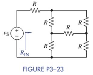
Chapter 3, Problem 3.23P
Use simple engineering intuition to find the input resistance of the circuit in Figure P3—23. Use either node-voltage or mesh-current analysis to prove your intuition. (Hint. It is a balanced bridge.)
Expert Solution & Answer
Want to see the full answer?
Check out a sample textbook solution
Students have asked these similar questions
Refer to circuit in Figure Q2, show to provUTM
UTM
points AB by the voltmeter is related to the true voltage E, by the following
that the voltage E, measured across
UTM
&UTM & UTM
Em
UTM
RM (R₁ + R₂)
E R₁ (R₂ + RM) + R₂RM
& UTM & UT
R₁
A
8 UTM
Voltmeter
8 UTM
ii.
8 UTM expression:
8 UTM 88 UTM
Voltage (V
source
UTM & UTM
8 UTM 8 D.C.
8 UTM 81
R₂
omy
Rm
B
UTM
Figure Q2: Voltage measurement circuit & UTM
UTM & UT
UTMUT
UTM & UT
UT
Virtual Lab: circuits and Kirchoff’s rules
Go to: https://phet.colorado.edu/it/simulation/circuit-construction-kit-dc-virtual-labBuild each of the circuits in the figures, with the designed characteristics.For each of the circuits, show the calculations to find the current and the potential difference in eachelement of the circuit.In building the circuit in Figure 1) through the simulator, adjust the small resistance of the battery tozero and put in series a small resistance as required from the design.For instance, for E1 you will need abattery with V = 6V and you will need to put in series a small resistance of 0.5 Ω to simulate the smallresistance in a battery.Figure 1)Figure 2)
After solving for the total resistance, and the applied voltage being a given for the circuit, the next logical step is to .....? so that individual component voltages and currents can be found.
Chapter 3 Solutions
ANALYSIS+DESIGN OF LINEAR CIRCUITS(LL)
Ch. 3 - Formulate node-voltage equations for the circuit...Ch. 3 - (a) Formulate node-voltage equations for the...Ch. 3 - (a) Formulate node-voltage equations for the...Ch. 3 - Formulate node-voltage equations for the circuit...Ch. 3 - (a) Formulate node-voltage equations for the...Ch. 3 - Choose a ground wisely and formulate node-voltage...Ch. 3 - The following are a set of node-voltage equations;...Ch. 3 - Choose a ground wisely and formulate node-voltage...Ch. 3 - Formulate node-voltage equations for the circuit...Ch. 3 - Formulate node-voltage equations for the circuit...
Ch. 3 - (a) Formulate mesh-current equations for the...Ch. 3 - (a) Formulate mesh-current equations for the...Ch. 3 - (a) Formulate mesh-current equations for the...Ch. 3 - Prob. 3.16PCh. 3 - Formulate mesh-current equations for the circuit...Ch. 3 - For the circuit of figure P3-19 solve for iA,iB,...Ch. 3 - Formulate mesh-current equations for the circuit...Ch. 3 - The circuit in Figure P3-21 seems to require two...Ch. 3 - Formulate mesh-current equations for the circuit...Ch. 3 - Use simple engineering intuition to find the input...Ch. 3 - In Figure P3-24 all of the resistors are 1k and...Ch. 3 - Use Figure P3-24 and MATLAB to solve the following...Ch. 3 - Formulate mesh-current equations for the circuit...Ch. 3 - Find vO for the block diagram shown in figure...Ch. 3 - Design a voltage-divider circuit that will realize...Ch. 3 - Design a current-divider circuit that will realize...Ch. 3 - Using a single resistor, design a circuit that...Ch. 3 - Find the proportionality constant K=vO/vS for the...Ch. 3 - Find the proportionality constant K=iO/vS for the...Ch. 3 - Find the proportionality constant K=vO/iS for the...Ch. 3 - Find the proportionality constant K=iO/iS for the...Ch. 3 - Find the proportionality constant K=vO/vS for the...Ch. 3 - Use the unit output method to find K and vO in...Ch. 3 - Use the unit output method to find K and vO in...Ch. 3 - Use the unit output method to find K in Figure...Ch. 3 - Use the superposition principle to find vO in...Ch. 3 - Use the superposition principle to find vO in...Ch. 3 - Use the superposition principle to find vO in...Ch. 3 - (a) Use the superposition principle to find vO in...Ch. 3 - A linear circuit containing two sources drives a...Ch. 3 - A block diagram of a linear circuit is shown in...Ch. 3 - A certain linear circuit has four input voltages...Ch. 3 - When the current source is turned off in the...Ch. 3 - For the circuit in Figure P3—51, find the Thévenin...Ch. 3 - For the circuit in Figure P3—52, find the Thévenin...Ch. 3 - For the circuit of Figure P3—53, find the Thévenin...Ch. 3 - Find the Thévenin or Norton equivalent circuit...Ch. 3 - Find the Thévenin or Norton equivalent circuit...Ch. 3 - Find the Thévenin equivalent circuit seen by RL in...Ch. 3 - Find the Norton equivalent seen by RL in Figure...Ch. 3 - You need to determine the Thévenin equivalent...Ch. 3 - Find the Thévenin equivalent seen by RL in figure...Ch. 3 - The purpose of this problem is to use Thévenin...Ch. 3 - The circuit in Figure P3-62 was solved earlier...Ch. 3 - Assume that Figure P3-63 represents a model of the...Ch. 3 - The iv characteristic of the active circuit...Ch. 3 - You have successfully completed the first course...Ch. 3 - The Thévenin equivalent parameters of a practical...Ch. 3 - Use a sequence of source transformations to find...Ch. 3 - The circuit in Figure P3-68 provides power to a...Ch. 3 - A nonlinear resistor is connected across a...Ch. 3 - Prob. 3.71PCh. 3 - Find the Norton equivalent seen by RL in Figure...Ch. 3 - Find the Thévenin equivalent seen by RL in Figure...Ch. 3 - Find the Thévenin equivalent seen by RL in Figure...Ch. 3 - For the circuit of Figure P3-75, find the value of...Ch. 3 - For the circuit of Figure P3-76, find the value of...Ch. 3 - The resistance R in Figure P3-77 is adjusted until...Ch. 3 - When a 5-k resistor is connected across a...Ch. 3 - Find the value of R in the circuit of Figure P3-79...Ch. 3 - For the circuit of Figure P3-80, find the value of...Ch. 3 - A 1-k load needs 10 mA to operate correctly....Ch. 3 - A practical source delivers 25 mA to a load. The...Ch. 3 - A 10-V source is shown in Figure P3-83 that is...Ch. 3 - (a)Select RL and design an interface circuit for...Ch. 3 - The source in Figure P3-85 has a 100-mA output...Ch. 3 - Figure P3-86 shows an interface circuit connecting...Ch. 3 - Prob. 3.87PCh. 3 - In this problem, you will design two interface...Ch. 3 - Two teams are competing to design the interface...Ch. 3 - The bridge-T attenuation pad shown in FigureP3-90...Ch. 3 - Design two interface circuits in Figure P3-91 so...Ch. 3 - Design the interface circuit in Figure P3-91 so...Ch. 3 - Design the interface circuit in Figure P3-93 so...Ch. 3 - It is claimed that both interface circuits in...Ch. 3 - Audio Speaker Resistance-Matching Network A...Ch. 3 - Interface Circuit Design Using no more than three...Ch. 3 - Battery Design A satellite requires a battery with...Ch. 3 - Design Interface Competition The output of a...Ch. 3 - Prob. 3.106IP
Knowledge Booster


Learn more about
Need a deep-dive on the concept behind this application? Look no further. Learn more about this topic, electrical-engineering and related others by exploring similar questions and additional content below.Similar questions
- Derive the Vout of the circuit shown in Figure 3 below in terms of V1, V2, R1and Rf. States all your assumptions. (Show steps by steps)arrow_forwardThe coil of a measuring instrument has a resistance of 1-ohm and the instrument has a full scale deflection of 250 V when a resistance of 4999 is connected with it. Draw a circuit by using given data and Solve it to find the full scale current of the PMMC meter when used as voltmeter.arrow_forward(i) i(0), v(0) (ii) a, o and circuit response (ii) dv(0)/dt (iv) v(0) (v) v(t) 20 40mF= v(t) 2u(-t)A (1) O40u(t)V 1H Figure Q2(b): Second order circuitarrow_forward
- Home Work: P1 Two resistors must be selected so that the current in one is four times the current in the other. If.. their equivalent parallel resistance is 5kr, calculate R and R₂.. Ans: 6.25k,25k]arrow_forwardCalculate the expression of the output resistance in terms of R in the circuit given below (hint: You can also find the resistance value by using one of the simulation methods. You can give the value instead of R and see the result on the screen.arrow_forwardAnalyze and redraw the complex circuit into a simple circuit diagram. At circuits #1 and #2, solve for: a. Rt b.It c.V at 5 ohm resistor d.I at 5 ohm resistor e.P at 5 ohm resistorarrow_forward
- An RTD forms one arm of a Wheatstone bridge, as shown in the figure below and the RTD is used to measure a constant temperature with the bridge operated in deflection mode. The bridge is balanced when the RTD temperature is at 0°C and the resistance R1 is set to 20 N. The RTD has a resistance of 20 2 at 0°C with an a = 0.0045°C-1. If the RTD is subjected to a temperature of 120°C and the output voltage from the bridge is 1.2 Volts, what is the input voltage? R₂ R₁ E₁ Hilllo R3 RTD RRTDarrow_forwardSubject: Circuits INote:support the problems with circuit diagram and label the pertinent partswith full solution so that i can follow the stepsarrow_forwardUsing the circuit in the figure, the experimentercalculates the internal resistance Rx of the structure “X” as“U/I” (U and I: Readings of the instruments). Can you please explain the solution in detail? Thanksarrow_forward
- Show complete and step by step solution. It is basic electrical engineering subj.arrow_forwardConstruct the circuit of figure P3-2 using the bipolar junction transistor (BJT). Please typing format solutionarrow_forwardc) Using minimum number of components, design a voltage divider which can deliver 1 W at 100V, 2W at -50V and 1.6W at -80V. The voltage source has an internal resistance of 200 Q and supplies a current of 100mA. What is the open - circuit voltage of the voltage source? All resistance in ohm.arrow_forward
arrow_back_ios
SEE MORE QUESTIONS
arrow_forward_ios
Recommended textbooks for you
 Introductory Circuit Analysis (13th Edition)Electrical EngineeringISBN:9780133923605Author:Robert L. BoylestadPublisher:PEARSON
 Delmar's Standard Textbook Of ElectricityElectrical EngineeringISBN:9781337900348Author:Stephen L. HermanPublisher:Cengage Learning
 Programmable Logic ControllersElectrical EngineeringISBN:9780073373843Author:Frank D. PetruzellaPublisher:McGraw-Hill Education
 Fundamentals of Electric CircuitsElectrical EngineeringISBN:9780078028229Author:Charles K Alexander, Matthew SadikuPublisher:McGraw-Hill Education
 Electric Circuits. (11th Edition)Electrical EngineeringISBN:9780134746968Author:James W. Nilsson, Susan RiedelPublisher:PEARSON
 Engineering ElectromagneticsElectrical EngineeringISBN:9780078028151Author:Hayt, William H. (william Hart), Jr, BUCK, John A.Publisher:Mcgraw-hill Education,
Introductory Circuit Analysis (13th Edition)
Electrical Engineering
ISBN:9780133923605
Author:Robert L. Boylestad
Publisher:PEARSON
Delmar's Standard Textbook Of Electricity
Electrical Engineering
ISBN:9781337900348
Author:Stephen L. Herman
Publisher:Cengage Learning
Programmable Logic Controllers
Electrical Engineering
ISBN:9780073373843
Author:Frank D. Petruzella
Publisher:McGraw-Hill Education
Fundamentals of Electric Circuits
Electrical Engineering
ISBN:9780078028229
Author:Charles K Alexander, Matthew Sadiku
Publisher:McGraw-Hill Education
Electric Circuits. (11th Edition)
Electrical Engineering
ISBN:9780134746968
Author:James W. Nilsson, Susan Riedel
Publisher:PEARSON
Engineering Electromagnetics
Electrical Engineering
ISBN:9780078028151
Author:Hayt, William H. (william Hart), Jr, BUCK, John A.
Publisher:Mcgraw-hill Education,
Nodal Analysis for Circuits Explained; Author: Engineer4Free;https://www.youtube.com/watch?v=f-sbANgw4fo;License: Standard Youtube License