
ANALYSIS+DESIGN OF LINEAR CIRCUITS(LL)
8th Edition
ISBN: 9781119235385
Author: Thomas
Publisher: WILEY
expand_more
expand_more
format_list_bulleted
Concept explainers
Videos
Textbook Question
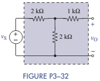
Chapter 3, Problem 3.32P
Find the proportionality constant
Expert Solution & Answer
Want to see the full answer?
Check out a sample textbook solution
Students have asked these similar questions
Find the transfer function and the dynamical-equation description of the network
in Figure P3-23. Do you think the transfer function is a good description of this system?
Also answer why you think the transfer function is/is not a good description; how would your answer change if the
active resistor of resistance -1 ohm is replaced by a passive resistor of resistance +1 ohm?
1 F
-1 S2
Current
source
I F
Figure P3-23
Please help me solve the A and B options. Answer which option you belong to. Just use multisim as a simulation. Thanks for your answers.
ww-
ATE
8-
TH The circuitshown-in-Figure-has-been-
connected-fora-long-time.
--R
What is the-current-passing-through the-18-N-resistor?a
A)
1.8-A
7.27-A
B)
C)
3.27-A
D)
4 A
2.67A
E)
Chapter 3 Solutions
ANALYSIS+DESIGN OF LINEAR CIRCUITS(LL)
Ch. 3 - Formulate node-voltage equations for the circuit...Ch. 3 - (a) Formulate node-voltage equations for the...Ch. 3 - (a) Formulate node-voltage equations for the...Ch. 3 - Formulate node-voltage equations for the circuit...Ch. 3 - (a) Formulate node-voltage equations for the...Ch. 3 - Choose a ground wisely and formulate node-voltage...Ch. 3 - The following are a set of node-voltage equations;...Ch. 3 - Choose a ground wisely and formulate node-voltage...Ch. 3 - Formulate node-voltage equations for the circuit...Ch. 3 - Formulate node-voltage equations for the circuit...
Ch. 3 - (a) Formulate mesh-current equations for the...Ch. 3 - (a) Formulate mesh-current equations for the...Ch. 3 - (a) Formulate mesh-current equations for the...Ch. 3 - Prob. 3.16PCh. 3 - Formulate mesh-current equations for the circuit...Ch. 3 - For the circuit of figure P3-19 solve for iA,iB,...Ch. 3 - Formulate mesh-current equations for the circuit...Ch. 3 - The circuit in Figure P3-21 seems to require two...Ch. 3 - Formulate mesh-current equations for the circuit...Ch. 3 - Use simple engineering intuition to find the input...Ch. 3 - In Figure P3-24 all of the resistors are 1k and...Ch. 3 - Use Figure P3-24 and MATLAB to solve the following...Ch. 3 - Formulate mesh-current equations for the circuit...Ch. 3 - Find vO for the block diagram shown in figure...Ch. 3 - Design a voltage-divider circuit that will realize...Ch. 3 - Design a current-divider circuit that will realize...Ch. 3 - Using a single resistor, design a circuit that...Ch. 3 - Find the proportionality constant K=vO/vS for the...Ch. 3 - Find the proportionality constant K=iO/vS for the...Ch. 3 - Find the proportionality constant K=vO/iS for the...Ch. 3 - Find the proportionality constant K=iO/iS for the...Ch. 3 - Find the proportionality constant K=vO/vS for the...Ch. 3 - Use the unit output method to find K and vO in...Ch. 3 - Use the unit output method to find K and vO in...Ch. 3 - Use the unit output method to find K in Figure...Ch. 3 - Use the superposition principle to find vO in...Ch. 3 - Use the superposition principle to find vO in...Ch. 3 - Use the superposition principle to find vO in...Ch. 3 - (a) Use the superposition principle to find vO in...Ch. 3 - A linear circuit containing two sources drives a...Ch. 3 - A block diagram of a linear circuit is shown in...Ch. 3 - A certain linear circuit has four input voltages...Ch. 3 - When the current source is turned off in the...Ch. 3 - For the circuit in Figure P3—51, find the Thévenin...Ch. 3 - For the circuit in Figure P3—52, find the Thévenin...Ch. 3 - For the circuit of Figure P3—53, find the Thévenin...Ch. 3 - Find the Thévenin or Norton equivalent circuit...Ch. 3 - Find the Thévenin or Norton equivalent circuit...Ch. 3 - Find the Thévenin equivalent circuit seen by RL in...Ch. 3 - Find the Norton equivalent seen by RL in Figure...Ch. 3 - You need to determine the Thévenin equivalent...Ch. 3 - Find the Thévenin equivalent seen by RL in figure...Ch. 3 - The purpose of this problem is to use Thévenin...Ch. 3 - The circuit in Figure P3-62 was solved earlier...Ch. 3 - Assume that Figure P3-63 represents a model of the...Ch. 3 - The iv characteristic of the active circuit...Ch. 3 - You have successfully completed the first course...Ch. 3 - The Thévenin equivalent parameters of a practical...Ch. 3 - Use a sequence of source transformations to find...Ch. 3 - The circuit in Figure P3-68 provides power to a...Ch. 3 - A nonlinear resistor is connected across a...Ch. 3 - Prob. 3.71PCh. 3 - Find the Norton equivalent seen by RL in Figure...Ch. 3 - Find the Thévenin equivalent seen by RL in Figure...Ch. 3 - Find the Thévenin equivalent seen by RL in Figure...Ch. 3 - For the circuit of Figure P3-75, find the value of...Ch. 3 - For the circuit of Figure P3-76, find the value of...Ch. 3 - The resistance R in Figure P3-77 is adjusted until...Ch. 3 - When a 5-k resistor is connected across a...Ch. 3 - Find the value of R in the circuit of Figure P3-79...Ch. 3 - For the circuit of Figure P3-80, find the value of...Ch. 3 - A 1-k load needs 10 mA to operate correctly....Ch. 3 - A practical source delivers 25 mA to a load. The...Ch. 3 - A 10-V source is shown in Figure P3-83 that is...Ch. 3 - (a)Select RL and design an interface circuit for...Ch. 3 - The source in Figure P3-85 has a 100-mA output...Ch. 3 - Figure P3-86 shows an interface circuit connecting...Ch. 3 - Prob. 3.87PCh. 3 - In this problem, you will design two interface...Ch. 3 - Two teams are competing to design the interface...Ch. 3 - The bridge-T attenuation pad shown in FigureP3-90...Ch. 3 - Design two interface circuits in Figure P3-91 so...Ch. 3 - Design the interface circuit in Figure P3-91 so...Ch. 3 - Design the interface circuit in Figure P3-93 so...Ch. 3 - It is claimed that both interface circuits in...Ch. 3 - Audio Speaker Resistance-Matching Network A...Ch. 3 - Interface Circuit Design Using no more than three...Ch. 3 - Battery Design A satellite requires a battery with...Ch. 3 - Design Interface Competition The output of a...Ch. 3 - Prob. 3.106IP
Knowledge Booster


Learn more about
Need a deep-dive on the concept behind this application? Look no further. Learn more about this topic, electrical-engineering and related others by exploring similar questions and additional content below.Similar questions
- You have a voltage source of 10 V and require a voltage of 8 V for the (very largeresistance) load you would add to the circuit. Design a voltage divider to create thisoutput–draw the circuit and label all elements with their values. You do not need toinclude the load resistance. Demonstrate that your choices lead to the desired outcome(using math).arrow_forwardSolve this ASAP FIGURE is also attacharrow_forwardIn the circuit shown in the figure, the variable resistance Ro is set for maximum power transfer. a) Find the Ro value b) Find the maximum power that can be transferred to Ro. Drarrow_forward
- Interface Circuit Design 3-24 KE Audio Speaker Resistance-Matching Network A company is producing an interface network that they claim would result in an Rin of 600 2 ±2% and RoUT of 16, 8, or 40 ±2%-depending on whether the connected speakers are 16, 8, or 4 S2-selectable via a built-in switch. The design is shown in Figure P3-24. Prove or disprove their claim. 600 2 592 2 8 Ω 16 Ω vs 4Ω 4Ω 4Ω |16, 8, or 4 2 Audio matching network FIGURE P3–24arrow_forwardPROBLEM 4. In the circuit below, R3 = 10 k2. Calculate the steady-state voltage across each circuit element. -20V R3 www R2 -5kQ C1 :6μF R1 >8kQarrow_forwardcan you help me find a solution for future problems on how to solve in the future. Need to find the values of R3 and RT and find the total voltage.arrow_forward
- The expression for power is given as the derivative of energy with respect to time. We have studied linear time invariant passive circuits in this course. Which of the following statement expresses the use of power and energy relations in a comprehensive way?Single choice. These can be used for passive and linear circuits These can be used for passive and active linear circuits These can be used for passive linear and non linear circuits These can be used for active and passive nonlinear and linear circuitsarrow_forwardUse the principles of superposition to find the current going through R3.arrow_forwardThe circuit of the given figure realizes the function (with figure*) A C -Y E Select one: O a. AB+C+DE b. AB+C. (D+E) O c. (A'+B').C+ (DE) o d. A'+B'+C'+D'+E'arrow_forward
- Find the equation for calculating what impedance R2 needs to have to obtain a “null measurement” at the voltmeter. Report the value of R2.arrow_forwardR3-50 Q UTM b) Figure Q4(b) is referred. By using nodal analysis, solve for: 5 UTM i) the values of voltage V, and V; in 5 UTM & UTM ii) the values of current, Ij in phasor domain and time domain UTM MS UTM 5 UTS 5 UTM 5 UTM 5 UTM & UTM 8 UTM 8 UTM 8 UTM 5 UTM 8 UTM 8 UTM R=10 Q UTM & UTM 8 UTM 8 UTM 8 U U XL=j5 Q 8 UTMSN 10020° v A 5 UTM 6 UTM R-20 Q R;=10 Q UTM 5 UTM M 8 UTM JUTM 8 UT 8 UTM 5 UM 8 UTM 5 UTM UTM UTM 8 UTM I-520° A UTM TM 8 UTM UTM 5 UTarrow_forwardA circuit consisting of three ideal batteries with voltages E1, E2, and E3, and three ideal resistors with resistances R1, R2, and R3, is shown in the figure below. Find Ip through point P with "up" being positive.arrow_forward
arrow_back_ios
SEE MORE QUESTIONS
arrow_forward_ios
Recommended textbooks for you
 Introductory Circuit Analysis (13th Edition)Electrical EngineeringISBN:9780133923605Author:Robert L. BoylestadPublisher:PEARSON
 Delmar's Standard Textbook Of ElectricityElectrical EngineeringISBN:9781337900348Author:Stephen L. HermanPublisher:Cengage Learning
 Programmable Logic ControllersElectrical EngineeringISBN:9780073373843Author:Frank D. PetruzellaPublisher:McGraw-Hill Education
 Fundamentals of Electric CircuitsElectrical EngineeringISBN:9780078028229Author:Charles K Alexander, Matthew SadikuPublisher:McGraw-Hill Education
 Electric Circuits. (11th Edition)Electrical EngineeringISBN:9780134746968Author:James W. Nilsson, Susan RiedelPublisher:PEARSON
 Engineering ElectromagneticsElectrical EngineeringISBN:9780078028151Author:Hayt, William H. (william Hart), Jr, BUCK, John A.Publisher:Mcgraw-hill Education,
Introductory Circuit Analysis (13th Edition)
Electrical Engineering
ISBN:9780133923605
Author:Robert L. Boylestad
Publisher:PEARSON
Delmar's Standard Textbook Of Electricity
Electrical Engineering
ISBN:9781337900348
Author:Stephen L. Herman
Publisher:Cengage Learning
Programmable Logic Controllers
Electrical Engineering
ISBN:9780073373843
Author:Frank D. Petruzella
Publisher:McGraw-Hill Education
Fundamentals of Electric Circuits
Electrical Engineering
ISBN:9780078028229
Author:Charles K Alexander, Matthew Sadiku
Publisher:McGraw-Hill Education
Electric Circuits. (11th Edition)
Electrical Engineering
ISBN:9780134746968
Author:James W. Nilsson, Susan Riedel
Publisher:PEARSON
Engineering Electromagnetics
Electrical Engineering
ISBN:9780078028151
Author:Hayt, William H. (william Hart), Jr, BUCK, John A.
Publisher:Mcgraw-hill Education,
Thevenin's Theorem; Author: Neso Academy;https://www.youtube.com/watch?v=veAFVTIpKyM;License: Standard YouTube License, CC-BY