
ANALYSIS+DESIGN OF LINEAR CIRCUITS(LL)
8th Edition
ISBN: 9781119235385
Author: Thomas
Publisher: WILEY
expand_more
expand_more
format_list_bulleted
Concept explainers
Videos
Textbook Question
Chapter 3, Problem 3.65P
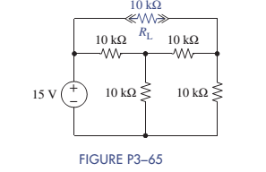
You have successfully completed the first course in Circuits I, and as part of an undergraduate work—study program your former professor has asked you to help her grade a Circuits 1 quiz. On the quiz, students were asked to find the power supplied by the source both to the
- Solve the quiz and establish reasonable A, B, C, D, and F cuts for incorrect solutions.
- A particular student correctly finds the Thévenin equivalent circuit seen by the resistive load and calculates the power to the load using
- Another student finds
- A third student first finds the Norton equivalent, and then finds the current through the load using a current divider and calculates the power in the load using
Expert Solution & Answer
Want to see the full answer?
Check out a sample textbook solution
Students have asked these similar questions
Two batteries are connected in parallel delivering power to a power resistor. The first battery has an open circuit voltage of 12.6 V and an internal resistance of 0.2 ohm. The second battery has an open circuit voltage of 12.2 V and an internal resistance of 0.3 ohm. Find the maximum power delivered to the load resistance.
The circuit shown in Figure DP 3-11 is designed to
help orange growers protect their crops against frost by sounding
an alarm when the temperature falls below freezing. It contains a
thermistor that has a resistance Ro=620 N at the temperature
To=20 °C=293 °K and ß= 3330 °K. (See problem DP 3-9.)
The alarm will sound when the voltage at the - input of
the comparator is less than the voltage at the + input. Using
voltage division twice, we see that the alarm sounds whenever
R2
R4
RT + R2
R3 +R4
Determine values of R2, R3, and R4 that cause the alarm to
sound when T = 50 °C
12 V
12 V
Thermistor
RT
R3
Buzzer
Comparator
RA
R2
Figure DP 3-11
Hi
Rp
Rp
V Bart
ww
a
b.
Rp
Rp
In Figure
Rp represents the resistance of the door knob on each of the 4 doors in the room. Rp =
500 N. RA represents the alarm. It has a resistance of 1.5 k2 and will sound an alarm when the voltage
across it reaches a magnitude above 1 V (i.e. Vob > 1 V or Vba > 1 V). The idea is that if a zombie touches
the door knob of one of the doors, it will act as a resistor in parallel with the resistance of the door knob.
zombie represents a resistance of 300 2.
1. AA batteries have a voltage of 1.5 V. What is the minimum number of AA batteries you need to connect
in series to create VBatt such that a zombie touching one of the door knobs sets off the alarm?
how could they open the doors without setting off the alarm
(you)?
ww
ww
ww
Chapter 3 Solutions
ANALYSIS+DESIGN OF LINEAR CIRCUITS(LL)
Ch. 3 - Formulate node-voltage equations for the circuit...Ch. 3 - (a) Formulate node-voltage equations for the...Ch. 3 - (a) Formulate node-voltage equations for the...Ch. 3 - Formulate node-voltage equations for the circuit...Ch. 3 - (a) Formulate node-voltage equations for the...Ch. 3 - Choose a ground wisely and formulate node-voltage...Ch. 3 - The following are a set of node-voltage equations;...Ch. 3 - Choose a ground wisely and formulate node-voltage...Ch. 3 - Formulate node-voltage equations for the circuit...Ch. 3 - Formulate node-voltage equations for the circuit...
Ch. 3 - (a) Formulate mesh-current equations for the...Ch. 3 - (a) Formulate mesh-current equations for the...Ch. 3 - (a) Formulate mesh-current equations for the...Ch. 3 - Prob. 3.16PCh. 3 - Formulate mesh-current equations for the circuit...Ch. 3 - For the circuit of figure P3-19 solve for iA,iB,...Ch. 3 - Formulate mesh-current equations for the circuit...Ch. 3 - The circuit in Figure P3-21 seems to require two...Ch. 3 - Formulate mesh-current equations for the circuit...Ch. 3 - Use simple engineering intuition to find the input...Ch. 3 - In Figure P3-24 all of the resistors are 1k and...Ch. 3 - Use Figure P3-24 and MATLAB to solve the following...Ch. 3 - Formulate mesh-current equations for the circuit...Ch. 3 - Find vO for the block diagram shown in figure...Ch. 3 - Design a voltage-divider circuit that will realize...Ch. 3 - Design a current-divider circuit that will realize...Ch. 3 - Using a single resistor, design a circuit that...Ch. 3 - Find the proportionality constant K=vO/vS for the...Ch. 3 - Find the proportionality constant K=iO/vS for the...Ch. 3 - Find the proportionality constant K=vO/iS for the...Ch. 3 - Find the proportionality constant K=iO/iS for the...Ch. 3 - Find the proportionality constant K=vO/vS for the...Ch. 3 - Use the unit output method to find K and vO in...Ch. 3 - Use the unit output method to find K and vO in...Ch. 3 - Use the unit output method to find K in Figure...Ch. 3 - Use the superposition principle to find vO in...Ch. 3 - Use the superposition principle to find vO in...Ch. 3 - Use the superposition principle to find vO in...Ch. 3 - (a) Use the superposition principle to find vO in...Ch. 3 - A linear circuit containing two sources drives a...Ch. 3 - A block diagram of a linear circuit is shown in...Ch. 3 - A certain linear circuit has four input voltages...Ch. 3 - When the current source is turned off in the...Ch. 3 - For the circuit in Figure P3—51, find the Thévenin...Ch. 3 - For the circuit in Figure P3—52, find the Thévenin...Ch. 3 - For the circuit of Figure P3—53, find the Thévenin...Ch. 3 - Find the Thévenin or Norton equivalent circuit...Ch. 3 - Find the Thévenin or Norton equivalent circuit...Ch. 3 - Find the Thévenin equivalent circuit seen by RL in...Ch. 3 - Find the Norton equivalent seen by RL in Figure...Ch. 3 - You need to determine the Thévenin equivalent...Ch. 3 - Find the Thévenin equivalent seen by RL in figure...Ch. 3 - The purpose of this problem is to use Thévenin...Ch. 3 - The circuit in Figure P3-62 was solved earlier...Ch. 3 - Assume that Figure P3-63 represents a model of the...Ch. 3 - The iv characteristic of the active circuit...Ch. 3 - You have successfully completed the first course...Ch. 3 - The Thévenin equivalent parameters of a practical...Ch. 3 - Use a sequence of source transformations to find...Ch. 3 - The circuit in Figure P3-68 provides power to a...Ch. 3 - A nonlinear resistor is connected across a...Ch. 3 - Prob. 3.71PCh. 3 - Find the Norton equivalent seen by RL in Figure...Ch. 3 - Find the Thévenin equivalent seen by RL in Figure...Ch. 3 - Find the Thévenin equivalent seen by RL in Figure...Ch. 3 - For the circuit of Figure P3-75, find the value of...Ch. 3 - For the circuit of Figure P3-76, find the value of...Ch. 3 - The resistance R in Figure P3-77 is adjusted until...Ch. 3 - When a 5-k resistor is connected across a...Ch. 3 - Find the value of R in the circuit of Figure P3-79...Ch. 3 - For the circuit of Figure P3-80, find the value of...Ch. 3 - A 1-k load needs 10 mA to operate correctly....Ch. 3 - A practical source delivers 25 mA to a load. The...Ch. 3 - A 10-V source is shown in Figure P3-83 that is...Ch. 3 - (a)Select RL and design an interface circuit for...Ch. 3 - The source in Figure P3-85 has a 100-mA output...Ch. 3 - Figure P3-86 shows an interface circuit connecting...Ch. 3 - Prob. 3.87PCh. 3 - In this problem, you will design two interface...Ch. 3 - Two teams are competing to design the interface...Ch. 3 - The bridge-T attenuation pad shown in FigureP3-90...Ch. 3 - Design two interface circuits in Figure P3-91 so...Ch. 3 - Design the interface circuit in Figure P3-91 so...Ch. 3 - Design the interface circuit in Figure P3-93 so...Ch. 3 - It is claimed that both interface circuits in...Ch. 3 - Audio Speaker Resistance-Matching Network A...Ch. 3 - Interface Circuit Design Using no more than three...Ch. 3 - Battery Design A satellite requires a battery with...Ch. 3 - Design Interface Competition The output of a...Ch. 3 - Prob. 3.106IP
Knowledge Booster


Learn more about
Need a deep-dive on the concept behind this application? Look no further. Learn more about this topic, electrical-engineering and related others by exploring similar questions and additional content below.Similar questions
- A studrnt wants to measure the voltage across the resistor R2 // R3 for the circuit below. Where should a student hook up a voltmeter to measure the voltage across R2 // R3?arrow_forwardEach of the cells shown in the figure has an emf of 1.50 V and a 0.0750-ohm internalresistance. Find I1, I2, and I3.arrow_forwardCAN YOU SOLVE THIS QUICKLTY In the circuit shown in the figure, OPAMP is fed from a 15 V source. VS voltage applied to the input of the circuitPlot the VO change depending on the change.arrow_forward
- 2- Describe the series-parallel combination between points A and D in Figure R2 R3 R1 Ao W R4 R6 R5 Doarrow_forwardInitially a 10 V battery is in series with a 100 ohm resistor and a 2 mH inductor. After a long time, a switch is thrown to remove the battery from the circuit, and replacing it with another 100 ohm resistor (and so the inductor ends up with two 100 ohm resistors In series). What is the current at t=0 s (immediately after the switch is thrown)?What is the current at t=5 ms later?arrow_forwardplease have step by step solution and explain. for part c the answer is not up to scale, but please have the steps for that tooarrow_forward
- %3D For the following circuit, calculate the current through R5 and the voltage drop across R5. Use the following parameters for the circuit: Vs = 8 V, R1 = 48, R2 = 8, R2 = 4, R4 = 5, R5 = 20. Rz R3 R5 R4arrow_forwardRi P Rz E3 Ry R3 Ez a) Apply Kirchoff's law to the circuit and write down the linearly indepedent voltage equations. You must draw the diagram and show the direction of currents in each of the components. The emf's in the circuit have the values E = 3 V, E2 = 9V and E3 = 10 V. The resistors have the following value of resistances R = 22 2, R2 = 33 N, R3 = 112 and R4 = 11N. b) Find the current through the resistance R3. current Give your answer up to at least three significance digits, A c) Find the magnitude of potential difference across the points p and q (i.e. potential difference of point q relative to point p. ).. magnitude of potential difference Give your answer up to at least three significance digits. Varrow_forward3-26 Find the proportionality constant K = io/vo for the circuit in Figure P3-26. FIGURE P3–26 VS 500 Ω Μ 1 ΚΩ Μ ΣικΩ iotarrow_forward
- A variable resistive load has a 10-10092 range, and is connected across the load terminals of a circuit. This circuit has a Thevenin voltage and resistance of 150 V and 25 2, respectively. What should be the resistance of the variable resistive load so that it will consume 80% of the max power that this circuit can deliver? (Round-off to two decimal places)arrow_forwardWhich of the following statements are correct for the circuit below? Thanks to the capacitors I – C1 and C2, the voltage gain of the circuit increases. II – Capacitors C1 and C2 are coupling capacitors and provide an isolation function between AC and DC voltages in the circuit. Thanks to the III – RE resistor, the voltage gain of the circuit increases. Thanks to the IV – RE resistor, the stability of the circuit increases. The V – C3 Capacitor is a bypass capacitor and prevents the loss of voltage gain. Capacitor VI – C3 is a coupling capacitor and has no effect on the voltage gain in the circuit. VII – As the value of the source internal resistance Rs increases, the voltage gain decreases. VIII – The voltage gain decreases as the value of any RL load to be added to the circuit increasesarrow_forwardFind the voltage at node P in the following figure V1 4V 9V b) 8V c) 10V d) 11V O a. 8 O b. 9 Oc. 11 O d. 10arrow_forward
arrow_back_ios
SEE MORE QUESTIONS
arrow_forward_ios
Recommended textbooks for you
 Introductory Circuit Analysis (13th Edition)Electrical EngineeringISBN:9780133923605Author:Robert L. BoylestadPublisher:PEARSON
 Delmar's Standard Textbook Of ElectricityElectrical EngineeringISBN:9781337900348Author:Stephen L. HermanPublisher:Cengage Learning
 Programmable Logic ControllersElectrical EngineeringISBN:9780073373843Author:Frank D. PetruzellaPublisher:McGraw-Hill Education
 Fundamentals of Electric CircuitsElectrical EngineeringISBN:9780078028229Author:Charles K Alexander, Matthew SadikuPublisher:McGraw-Hill Education
 Electric Circuits. (11th Edition)Electrical EngineeringISBN:9780134746968Author:James W. Nilsson, Susan RiedelPublisher:PEARSON
 Engineering ElectromagneticsElectrical EngineeringISBN:9780078028151Author:Hayt, William H. (william Hart), Jr, BUCK, John A.Publisher:Mcgraw-hill Education,
Introductory Circuit Analysis (13th Edition)
Electrical Engineering
ISBN:9780133923605
Author:Robert L. Boylestad
Publisher:PEARSON
Delmar's Standard Textbook Of Electricity
Electrical Engineering
ISBN:9781337900348
Author:Stephen L. Herman
Publisher:Cengage Learning
Programmable Logic Controllers
Electrical Engineering
ISBN:9780073373843
Author:Frank D. Petruzella
Publisher:McGraw-Hill Education
Fundamentals of Electric Circuits
Electrical Engineering
ISBN:9780078028229
Author:Charles K Alexander, Matthew Sadiku
Publisher:McGraw-Hill Education
Electric Circuits. (11th Edition)
Electrical Engineering
ISBN:9780134746968
Author:James W. Nilsson, Susan Riedel
Publisher:PEARSON
Engineering Electromagnetics
Electrical Engineering
ISBN:9780078028151
Author:Hayt, William H. (william Hart), Jr, BUCK, John A.
Publisher:Mcgraw-hill Education,
Thevenin's Theorem; Author: Neso Academy;https://www.youtube.com/watch?v=veAFVTIpKyM;License: Standard YouTube License, CC-BY