
ANALYSIS+DESIGN OF LINEAR CIRCUITS(LL)
8th Edition
ISBN: 9781119235385
Author: Thomas
Publisher: WILEY
expand_more
expand_more
format_list_bulleted
Concept explainers
Videos
Textbook Question
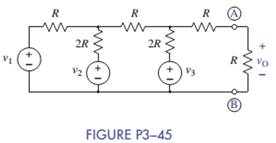
Chapter 3, Problem 3.45P
(a) Use the superposition principle to find
(b) Use MATLAB and node-voltage analysis to verify your answer symbolically.
Expert Solution & Answer
Want to see the full answer?
Check out a sample textbook solution
Students have asked these similar questions
With regard to the circuit represented in the following circuit, first transformboth voltage sources to current sources, reduce the number of elements asmuch as possible, and determine the voltage v3.
1. What is a combinational circuit?
2. Give examples circuits under combinational circuit.
3. What are the steps in designing a combinational circuit?
You have a voltage source of 10 V and require a voltage of 8 V for the (very largeresistance) load you would add to the circuit. Design a voltage divider to create thisoutput–draw the circuit and label all elements with their values. You do not need toinclude the load resistance. Demonstrate that your choices lead to the desired outcome(using math).
Chapter 3 Solutions
ANALYSIS+DESIGN OF LINEAR CIRCUITS(LL)
Ch. 3 - Formulate node-voltage equations for the circuit...Ch. 3 - (a) Formulate node-voltage equations for the...Ch. 3 - (a) Formulate node-voltage equations for the...Ch. 3 - Formulate node-voltage equations for the circuit...Ch. 3 - (a) Formulate node-voltage equations for the...Ch. 3 - Choose a ground wisely and formulate node-voltage...Ch. 3 - The following are a set of node-voltage equations;...Ch. 3 - Choose a ground wisely and formulate node-voltage...Ch. 3 - Formulate node-voltage equations for the circuit...Ch. 3 - Formulate node-voltage equations for the circuit...
Ch. 3 - (a) Formulate mesh-current equations for the...Ch. 3 - (a) Formulate mesh-current equations for the...Ch. 3 - (a) Formulate mesh-current equations for the...Ch. 3 - Prob. 3.16PCh. 3 - Formulate mesh-current equations for the circuit...Ch. 3 - For the circuit of figure P3-19 solve for iA,iB,...Ch. 3 - Formulate mesh-current equations for the circuit...Ch. 3 - The circuit in Figure P3-21 seems to require two...Ch. 3 - Formulate mesh-current equations for the circuit...Ch. 3 - Use simple engineering intuition to find the input...Ch. 3 - In Figure P3-24 all of the resistors are 1k and...Ch. 3 - Use Figure P3-24 and MATLAB to solve the following...Ch. 3 - Formulate mesh-current equations for the circuit...Ch. 3 - Find vO for the block diagram shown in figure...Ch. 3 - Design a voltage-divider circuit that will realize...Ch. 3 - Design a current-divider circuit that will realize...Ch. 3 - Using a single resistor, design a circuit that...Ch. 3 - Find the proportionality constant K=vO/vS for the...Ch. 3 - Find the proportionality constant K=iO/vS for the...Ch. 3 - Find the proportionality constant K=vO/iS for the...Ch. 3 - Find the proportionality constant K=iO/iS for the...Ch. 3 - Find the proportionality constant K=vO/vS for the...Ch. 3 - Use the unit output method to find K and vO in...Ch. 3 - Use the unit output method to find K and vO in...Ch. 3 - Use the unit output method to find K in Figure...Ch. 3 - Use the superposition principle to find vO in...Ch. 3 - Use the superposition principle to find vO in...Ch. 3 - Use the superposition principle to find vO in...Ch. 3 - (a) Use the superposition principle to find vO in...Ch. 3 - A linear circuit containing two sources drives a...Ch. 3 - A block diagram of a linear circuit is shown in...Ch. 3 - A certain linear circuit has four input voltages...Ch. 3 - When the current source is turned off in the...Ch. 3 - For the circuit in Figure P3—51, find the Thévenin...Ch. 3 - For the circuit in Figure P3—52, find the Thévenin...Ch. 3 - For the circuit of Figure P3—53, find the Thévenin...Ch. 3 - Find the Thévenin or Norton equivalent circuit...Ch. 3 - Find the Thévenin or Norton equivalent circuit...Ch. 3 - Find the Thévenin equivalent circuit seen by RL in...Ch. 3 - Find the Norton equivalent seen by RL in Figure...Ch. 3 - You need to determine the Thévenin equivalent...Ch. 3 - Find the Thévenin equivalent seen by RL in figure...Ch. 3 - The purpose of this problem is to use Thévenin...Ch. 3 - The circuit in Figure P3-62 was solved earlier...Ch. 3 - Assume that Figure P3-63 represents a model of the...Ch. 3 - The iv characteristic of the active circuit...Ch. 3 - You have successfully completed the first course...Ch. 3 - The Thévenin equivalent parameters of a practical...Ch. 3 - Use a sequence of source transformations to find...Ch. 3 - The circuit in Figure P3-68 provides power to a...Ch. 3 - A nonlinear resistor is connected across a...Ch. 3 - Prob. 3.71PCh. 3 - Find the Norton equivalent seen by RL in Figure...Ch. 3 - Find the Thévenin equivalent seen by RL in Figure...Ch. 3 - Find the Thévenin equivalent seen by RL in Figure...Ch. 3 - For the circuit of Figure P3-75, find the value of...Ch. 3 - For the circuit of Figure P3-76, find the value of...Ch. 3 - The resistance R in Figure P3-77 is adjusted until...Ch. 3 - When a 5-k resistor is connected across a...Ch. 3 - Find the value of R in the circuit of Figure P3-79...Ch. 3 - For the circuit of Figure P3-80, find the value of...Ch. 3 - A 1-k load needs 10 mA to operate correctly....Ch. 3 - A practical source delivers 25 mA to a load. The...Ch. 3 - A 10-V source is shown in Figure P3-83 that is...Ch. 3 - (a)Select RL and design an interface circuit for...Ch. 3 - The source in Figure P3-85 has a 100-mA output...Ch. 3 - Figure P3-86 shows an interface circuit connecting...Ch. 3 - Prob. 3.87PCh. 3 - In this problem, you will design two interface...Ch. 3 - Two teams are competing to design the interface...Ch. 3 - The bridge-T attenuation pad shown in FigureP3-90...Ch. 3 - Design two interface circuits in Figure P3-91 so...Ch. 3 - Design the interface circuit in Figure P3-91 so...Ch. 3 - Design the interface circuit in Figure P3-93 so...Ch. 3 - It is claimed that both interface circuits in...Ch. 3 - Audio Speaker Resistance-Matching Network A...Ch. 3 - Interface Circuit Design Using no more than three...Ch. 3 - Battery Design A satellite requires a battery with...Ch. 3 - Design Interface Competition The output of a...Ch. 3 - Prob. 3.106IP
Knowledge Booster


Learn more about
Need a deep-dive on the concept behind this application? Look no further. Learn more about this topic, electrical-engineering and related others by exploring similar questions and additional content below.Similar questions
- Consider the circuit diagram below. Solve for the current values and directions through R₁ and R4, and the voltage drop across R3 using mesh analysis. You may consider redrawing the circuit at the end of your analysis to better demonstrate polarities. Show your work and use Matlab to solve the system of equations that you generate. Be sure to include the commands you used in Matlab as part of your analysis. You must also use CircuitJS to verify your result. Attach an exported image or screen shot of your circuit from CircuitJS with the current and voltage "shown" (colors are shown on the diagram). E1 5V R1 1kΩ R2 5k Ω E2 20V R4 2k www R3 3Κ Ω R5 1kΩarrow_forward3. Consider the circuit diagram below. Solve for the mesh currents I1, I2, and 13 and the voltage at node a using mesh analysis. Show your work and use Matlab to solve the system of equations that you generate. Be sure to include the commands you used in Matlab as part of your analysis. You must also use CircuitJS to verify your result. Attach an exported image of your circuit from CircuitJS with the current and voltage "shown" (colors are shown on the diagram). R3 1 ΚΩ www 11 R₂₁ 4 ΚΩ www a R₂ 2 ΚΩ R₂₁ 1 ΚΩ www 12 E 100 V 13 R5 5 ΚΩarrow_forwardUse the principles of superposition to find the current going through R3.arrow_forward
- definition of Superposition Analysis, in which cases of circuits types it can be used, list two examples about its application in electrical engineering and show an electrical circuit “figure only” with no calculation, that can be solved using Superposition Analysis and explain theoretically how it would be solved.arrow_forwardQ3 Determine the circuit to produce the output voltage given by V=0.5V/₁-10 V₂+ V3 - V4-V5arrow_forwardConsider the circuit diagram below. Solve for the current values and directionsthrough R1 and R4, and the voltage drop across R3 using mesh analysis. You mayconsider redrawing the circuit at the end of your analysis to better demonstratepolarities. Show your work and use Matlab to solve the system of equations thatyou generate. Be sure to include the commands you used in Matlab as part ofyour analysis. You must also use CircuitJS to verify your result. Attach anexported image or screen shot of your circuit from CircuitJS with the current andvoltage “shown” (colors are shown on the diagram)arrow_forward
- Given this thevenin equivalent circuit, we now plug up a load resistor that is 500 ohms. How would you calculate output voltage and output current given this load resistor?arrow_forwardBasics of Electrical Engineering Assignment I Use Thevenin's Theorem to show that the current / in the R3 = 200 n resistance in the circuit shown below equals 300 m amp: R1 R2 750 1500 V1 R3 2000 V2 -80V -140V R5 R4 ww 2500 1250arrow_forwardIn the circuit given below, it is known that the maximum power is drawn from the circuit when the RL resistance is 30 Ohms. In this case, what is the value of R dinç? (Find the Thevenin equivalent.)arrow_forward
- can someone help me with this problem and show me how to get it done step by step write a complete set of node voltage equatiosn that can be used to solve the circuit belowarrow_forwardIn order to use the following circuit as a subtractor to find the difference between two signals without adding any gain to the difference then (V+V.) R, V, VA (V) Signal wires Vo Vg (0 V) (V) V2 R1=R2=R3=R4 R1=R2, R3=R4 R1=R3 , R2=R4 R1&R3 should equal to zeroarrow_forwardFind the equation for calculating what impedance R2 needs to have to obtain a “null measurement” at the voltmeter. Report the value of R2.arrow_forward
arrow_back_ios
SEE MORE QUESTIONS
arrow_forward_ios
Recommended textbooks for you
 Introductory Circuit Analysis (13th Edition)Electrical EngineeringISBN:9780133923605Author:Robert L. BoylestadPublisher:PEARSON
 Delmar's Standard Textbook Of ElectricityElectrical EngineeringISBN:9781337900348Author:Stephen L. HermanPublisher:Cengage Learning
 Programmable Logic ControllersElectrical EngineeringISBN:9780073373843Author:Frank D. PetruzellaPublisher:McGraw-Hill Education
 Fundamentals of Electric CircuitsElectrical EngineeringISBN:9780078028229Author:Charles K Alexander, Matthew SadikuPublisher:McGraw-Hill Education
 Electric Circuits. (11th Edition)Electrical EngineeringISBN:9780134746968Author:James W. Nilsson, Susan RiedelPublisher:PEARSON
 Engineering ElectromagneticsElectrical EngineeringISBN:9780078028151Author:Hayt, William H. (william Hart), Jr, BUCK, John A.Publisher:Mcgraw-hill Education,
Introductory Circuit Analysis (13th Edition)
Electrical Engineering
ISBN:9780133923605
Author:Robert L. Boylestad
Publisher:PEARSON
Delmar's Standard Textbook Of Electricity
Electrical Engineering
ISBN:9781337900348
Author:Stephen L. Herman
Publisher:Cengage Learning
Programmable Logic Controllers
Electrical Engineering
ISBN:9780073373843
Author:Frank D. Petruzella
Publisher:McGraw-Hill Education
Fundamentals of Electric Circuits
Electrical Engineering
ISBN:9780078028229
Author:Charles K Alexander, Matthew Sadiku
Publisher:McGraw-Hill Education
Electric Circuits. (11th Edition)
Electrical Engineering
ISBN:9780134746968
Author:James W. Nilsson, Susan Riedel
Publisher:PEARSON
Engineering Electromagnetics
Electrical Engineering
ISBN:9780078028151
Author:Hayt, William H. (william Hart), Jr, BUCK, John A.
Publisher:Mcgraw-hill Education,
Thevenin's Theorem; Author: Neso Academy;https://www.youtube.com/watch?v=veAFVTIpKyM;License: Standard YouTube License, CC-BY