
Introductory Circuit Analysis (13th Edition)
13th Edition
ISBN: 9780133923605
Author: Robert L. Boylestad
Publisher: PEARSON
expand_more
expand_more
format_list_bulleted
Related questions
Question

Transcribed Image Text:QUESTION 2
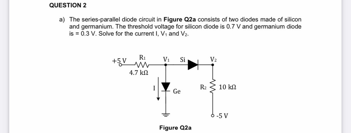
a) The series-parallel diode circuit in Figure Q2a consists of two diodes made of silicon
and germanium. The threshold voltage for silicon diode is 0.7 V and germanium diode
is = 0.3 V. Solve for the current I, V, and V2.
R1
V1
Si
V2
+5 V
4.7 kN
R2
10 kN
Ge
6 -5 V
Figure Q2a
Expert Solution
This question has been solved!
Explore an expertly crafted, step-by-step solution for a thorough understanding of key concepts.

This is a popular solution

Trending nowThis is a popular solution!

Step by stepSolved in 2 steps with 1 images

Knowledge Booster


Learn more about
Need a deep-dive on the concept behind this application? Look no further. Learn more about this topic, electrical-engineering and related others by exploring similar questions and additional content below.Similar questions
- Q*: Calculate the current through 48 Q resistor in the circuit shown in Figure(i).Assume the diodes to be of silicon and forward resistance of each diode is 1 Q. D D2 48 2 ww 10 V= D4 D3 (i)arrow_forwardAssuming ideal diode the voltage across the resistor R2 in the circuit shown in the Figure is: R1 E = +12V0- 2.2k2 RE1.8kN E, = +4V A 4.0 V 7.6 V 3.6 V D 4.4 Varrow_forwardWhat will be the process and full procedure to do it with answer?arrow_forward
- Diode circuitsFor each circuit below, use the diode approximation with forward dropVF= 0.7 V to find the output voltage. No current flows to the output.arrow_forwardA 3-phase full-wave bridge rectifier is built using six power diodes numbered 1 to 6. The phase sequence of the 3-phase source is ABC and the line to line voltage is 440 V. The line to neutral voltage of phase A has an angle of -30 degrees. The anodes of the diodes 1, 2, 3 are connected to phase A, B, and C, respectively, and the cathodes of diodes 1, 2, and 3 are connected to a common terminal that serves as the positive terminal of the rectifier's output. The cathodes of diodes 4, 5, and 6 are connected to phase A, B, and C, respectively, and the anodes of diodes 4, 5, and 6 are connected to a common terminal that serves as the negative terminal of the rectifier's output. If diode 1 is damaged and acts as an open circuit, what would the RMS voltage be at the load?arrow_forwardUsing the ideal diode model, find the output voltage for the input voltage of the following circuit and graph it in detail. (a) (b) R₁ D₁ www ww R3 D2 (a) R₁ D₁ www + + D2 R2 vo Vo R₂ (b)arrow_forward
- Determine the output voltage V out of the circuit shown in Figure. However, when the Zener diode is forward biased, the voltage of both ends is approximated to 0.7V.arrow_forwardAssuming an ideal diode model for all the diodes in the circuit below, chose the correct state (bias) for each diode. R1 ww 9kQ 1N1199C R2 D1 18kQ 1N1199C V2 12 V R3 1kQ D3 1N1199C R4 D3: On (Forward Bais) D3: Off (Reverse Bais)arrow_forwardFor the circuit in the figure, let V input = 8V, Ri = 12ohms, RL = 10ohms, and VZ = 3.3V. Determine the voltages and currents of the resistors and the current of the zener diode.arrow_forward
arrow_back_ios
SEE MORE QUESTIONS
arrow_forward_ios
Recommended textbooks for you
- Introductory Circuit Analysis (13th Edition)Electrical EngineeringISBN:9780133923605Author:Robert L. BoylestadPublisher:PEARSON
 Delmar's Standard Textbook Of ElectricityElectrical EngineeringISBN:9781337900348Author:Stephen L. HermanPublisher:Cengage Learning
 Programmable Logic ControllersElectrical EngineeringISBN:9780073373843Author:Frank D. PetruzellaPublisher:McGraw-Hill Education
  Fundamentals of Electric CircuitsElectrical EngineeringISBN:9780078028229Author:Charles K Alexander, Matthew SadikuPublisher:McGraw-Hill Education
 Electric Circuits. (11th Edition)Electrical EngineeringISBN:9780134746968Author:James W. Nilsson, Susan RiedelPublisher:PEARSON
 Engineering ElectromagneticsElectrical EngineeringISBN:9780078028151Author:Hayt, William H. (william Hart), Jr, BUCK, John A.Publisher:Mcgraw-hill Education,
Introductory Circuit Analysis (13th Edition)
Electrical Engineering
ISBN:9780133923605
Author:Robert L. Boylestad
Publisher:PEARSON
Delmar's Standard Textbook Of Electricity
Electrical Engineering
ISBN:9781337900348
Author:Stephen L. Herman
Publisher:Cengage Learning
Programmable Logic Controllers
Electrical Engineering
ISBN:9780073373843
Author:Frank D. Petruzella
Publisher:McGraw-Hill Education
Fundamentals of Electric Circuits
Electrical Engineering
ISBN:9780078028229
Author:Charles K Alexander, Matthew Sadiku
Publisher:McGraw-Hill Education
Electric Circuits. (11th Edition)
Electrical Engineering
ISBN:9780134746968
Author:James W. Nilsson, Susan Riedel
Publisher:PEARSON
Engineering Electromagnetics
Electrical Engineering
ISBN:9780078028151
Author:Hayt, William H. (william Hart), Jr, BUCK, John A.
Publisher:Mcgraw-hill Education,