
Microelectronics: Circuit Analysis and Design
4th Edition
ISBN: 9780073380643
Author: Donald A. Neamen
Publisher: McGraw-Hill Companies, The
expand_more
expand_more
format_list_bulleted
Videos
Textbook Question
Chapter 14, Problem 14.3P
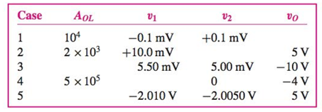
Data in the following table were taken for several op−amps operating in theopen−loop configuration. Determine the unknown variables in the table.
Expert Solution & Answer
Want to see the full answer?
Check out a sample textbook solution
Students have asked these similar questions
For the circuit in the figurea) Determine the time constant.b) Write the mathematical expression for IL, VL and VR, after the switch is closed.c) Determine IL, VL for one, three and five time constants.d) Draw the waveforms of IL, VL and VR.
sketch vL1 and vR2 on a graph. mark the labels in microseconds one time constant after the charging phase begins and the value of each voltage at that time
A single phase – half wave controlled rectifier with freewheeling diode is supplying a load consistingseries connected a resistor and an inductance from a 70.7V (RMS), 50Hz sinusoidal AC source.The firing delay of the thyristor is 90° and the load values are R=10Ω, L=0.1 H. Define the loadcurrent expression and draw the load current by calculating for first two periods. And calculate theaverage values of the load voltage and current.
Chapter 14 Solutions
Microelectronics: Circuit Analysis and Design
Ch. 14 - Using the circuit and transistor parameters of...Ch. 14 - Prob. 14.2TYUCh. 14 - Prob. 14.1EPCh. 14 - Determine the closedloop input resistance at the...Ch. 14 - For a noninverting amplifier, the resistances are...Ch. 14 - An opamp with an openloop gain of AOL=105 is used...Ch. 14 - Prob. 14.3TYUCh. 14 - An operational amplifier connected in a...Ch. 14 - Prob. 14.5TYUCh. 14 - Prob. 14.6TYU
Ch. 14 - Find the closedloop input resistance of a voltage...Ch. 14 - An opamp with openloop parameters of AOL=2105 and...Ch. 14 - A 0.5 V input step function is applied at t=0 to a...Ch. 14 - The slew rate of the 741 opamp is 0.63V/s ....Ch. 14 - Prob. 14.8TYUCh. 14 - Prob. 14.8EPCh. 14 - Consider the active load bipolar duffamp stage in...Ch. 14 - Prob. 14.10EPCh. 14 - Prob. 14.11EPCh. 14 - Prob. 14.12EPCh. 14 - For the opamp circuit shown in Figure 14.28, the...Ch. 14 - Prob. 14.9TYUCh. 14 - List and describe five practical opamp parameters...Ch. 14 - What is atypical value of openloop, lowfrequency...Ch. 14 - Prob. 3RQCh. 14 - Prob. 4RQCh. 14 - Prob. 5RQCh. 14 - Prob. 6RQCh. 14 - Describe the gainbandwidth product property of a...Ch. 14 - Define slew rate and define fullpower bandwidth.Ch. 14 - Prob. 9RQCh. 14 - What is one cause of an offset voltage in the...Ch. 14 - Prob. 11RQCh. 14 - Prob. 12RQCh. 14 - Prob. 13RQCh. 14 - Prob. 14RQCh. 14 - Prob. 15RQCh. 14 - Prob. 16RQCh. 14 - Prob. 17RQCh. 14 - Prob. 14.1PCh. 14 - Consider the opamp described in Problem 14.1. In...Ch. 14 - Data in the following table were taken for several...Ch. 14 - Prob. 14.4PCh. 14 - Prob. 14.5PCh. 14 - Prob. 14.6PCh. 14 - Prob. 14.7PCh. 14 - Prob. 14.8PCh. 14 - An inverting amplifier is fabricated using 0.1...Ch. 14 - For the opamp used in the inverting amplifier...Ch. 14 - Prob. 14.11PCh. 14 - Consider the two inverting amplifiers in cascade...Ch. 14 - The noninverting amplifier in Figure P14.13 has an...Ch. 14 - For the opamp in the voltage follower circuit in...Ch. 14 - The summing amplifier in Figure P14.15 has an...Ch. 14 - Prob. 14.16PCh. 14 - Prob. 14.18PCh. 14 - Prob. 14.19PCh. 14 - Prob. 14.20PCh. 14 - Prob. 14.21PCh. 14 - Prob. 14.22PCh. 14 - Three inverting amplifiers, each with R2=150k and...Ch. 14 - Prob. 14.24PCh. 14 - Prob. 14.25PCh. 14 - Prob. 14.26PCh. 14 - Prob. 14.27PCh. 14 - Prob. D14.28PCh. 14 - Prob. 14.29PCh. 14 - Prob. 14.30PCh. 14 - Prob. 14.31PCh. 14 - Prob. 14.32PCh. 14 - Prob. 14.33PCh. 14 - Prob. 14.34PCh. 14 - Prob. 14.35PCh. 14 - Prob. 14.36PCh. 14 - Prob. 14.37PCh. 14 - In the circuit in Figure P14.38, the offset...Ch. 14 - Prob. 14.39PCh. 14 - Prob. 14.40PCh. 14 - Prob. 14.41PCh. 14 - Prob. 14.42PCh. 14 - Prob. 14.43PCh. 14 - Prob. 14.44PCh. 14 - Prob. 14.46PCh. 14 - Prob. D14.47PCh. 14 - Prob. 14.48PCh. 14 - Prob. 14.50PCh. 14 - Prob. 14.51PCh. 14 - Prob. D14.52PCh. 14 - Prob. D14.53PCh. 14 - Prob. 14.55PCh. 14 - Prob. 14.56PCh. 14 - Prob. 14.57PCh. 14 - The opamp in the difference amplifier...Ch. 14 - Prob. 14.61P
Knowledge Booster


Learn more about
Need a deep-dive on the concept behind this application? Look no further. Learn more about this topic, electrical-engineering and related others by exploring similar questions and additional content below.Similar questions
- In the circuit of the following figure, the input voltage Vs is 15 volts rms with a frequency of 60 Hz, R equals 150 Ohms and C equals 100,000 Pico Farads. The diodes are Germanium (Vd = 0.2 volts) and the Zener diode is 12 volts. a) The magnitude of the ripple voltage at Cb) The Magnitude of the Peak Inverse Voltage (PIV) for D1 and D2.arrow_forwarda) Write the expression for the voltage vC after the switch is closed b) Write the expression for the current iC after the switch is closed. Plot the results of parts (a) and (b).arrow_forwardIn the figure given we have u(t)=10· coswt [V]. We assume the diodesand the A-meter (A) to be ideal.a) Plot the waveform of the current flowing through the A-m in scale.b) What is the reading of the A-m, if it is moving-coil type?c) What is the reading of the A-m, if it is moving-iron type?d) Calculate the power factor of the WHOLE structure.arrow_forward
- Example A NTC thermistor has a resistance of 30 KN at 0°C and material temperature constant 3575 K. calculate the value of the thermistor resistance at 25°C. Given NTC- thermistor husarrow_forwardQuestion 15 In half wave rectifier with filter, if the capacitance is increased, the ripple factor increases. True False Moving to another question will save this response. iparrow_forwardThree Phase Uncontrolled Half Wave Rectifiers find the value of Voltage and Currents (output de and Root Mean Square) with all the proved, then sketch the curve from 0-2 on these axes (vs, vo, ia, ib, ic, io) explain its operation.arrow_forward
- Questions: 1. Are the experimental and theoretical values of voltages and currents match? Indicate the percentage of differences. 2. Give possible reasons for any discrepanciesarrow_forwardFundamentals of Electric Circuitarrow_forwardPower supply circuit is delivering 0.5 A and an average voltage 20 V to the load as shown in the circuit below. The ripple voltage of the half wave rectifier is 0.5 V and the diode is represented using constant voltage model. The smoothing capacitor value is equal to 220V rmsh soHz} VL-DC =20V 0.01 F 0.02 F 0.0167 F None of the abovearrow_forward
- 5) For a single phase full wave bridge rectifier with a resistive load if the input voltage is 125 V, 60 Hz with the value of resistance is 20 ohms. Compute the value of rms value of load voltage and average value of load voltage by formulating the equations with all steps (uncontrolled)arrow_forwardIf we have a voltmeter, during the measurement do we need a voltmeter with high or low input impedance to measure current. How about when we need to measure voltage drop. Please explain. ..arrow_forwardA three-phase rectifier is supplied by a 173.2-V rms line-to-line 60-Hz source. The RL load is a 100 resistor in series with a 15-mH inductor. Determine THD taking Is1 = 1.35arrow_forward
arrow_back_ios
SEE MORE QUESTIONS
arrow_forward_ios
Recommended textbooks for you
 Introductory Circuit Analysis (13th Edition)Electrical EngineeringISBN:9780133923605Author:Robert L. BoylestadPublisher:PEARSON
 Delmar's Standard Textbook Of ElectricityElectrical EngineeringISBN:9781337900348Author:Stephen L. HermanPublisher:Cengage Learning
 Programmable Logic ControllersElectrical EngineeringISBN:9780073373843Author:Frank D. PetruzellaPublisher:McGraw-Hill Education
 Fundamentals of Electric CircuitsElectrical EngineeringISBN:9780078028229Author:Charles K Alexander, Matthew SadikuPublisher:McGraw-Hill Education
 Electric Circuits. (11th Edition)Electrical EngineeringISBN:9780134746968Author:James W. Nilsson, Susan RiedelPublisher:PEARSON
 Engineering ElectromagneticsElectrical EngineeringISBN:9780078028151Author:Hayt, William H. (william Hart), Jr, BUCK, John A.Publisher:Mcgraw-hill Education,
Introductory Circuit Analysis (13th Edition)
Electrical Engineering
ISBN:9780133923605
Author:Robert L. Boylestad
Publisher:PEARSON
Delmar's Standard Textbook Of Electricity
Electrical Engineering
ISBN:9781337900348
Author:Stephen L. Herman
Publisher:Cengage Learning
Programmable Logic Controllers
Electrical Engineering
ISBN:9780073373843
Author:Frank D. Petruzella
Publisher:McGraw-Hill Education
Fundamentals of Electric Circuits
Electrical Engineering
ISBN:9780078028229
Author:Charles K Alexander, Matthew Sadiku
Publisher:McGraw-Hill Education
Electric Circuits. (11th Edition)
Electrical Engineering
ISBN:9780134746968
Author:James W. Nilsson, Susan Riedel
Publisher:PEARSON
Engineering Electromagnetics
Electrical Engineering
ISBN:9780078028151
Author:Hayt, William H. (william Hart), Jr, BUCK, John A.
Publisher:Mcgraw-hill Education,
Diode Logic Gates - OR, NOR, AND, & NAND; Author: The Organic Chemistry Tutor;https://www.youtube.com/watch?v=9lqwSaIDm2g;License: Standard Youtube License