
Videos
Consider the two inverting amplifiers in cascade in Figure P14.12. The op−amp parameters are
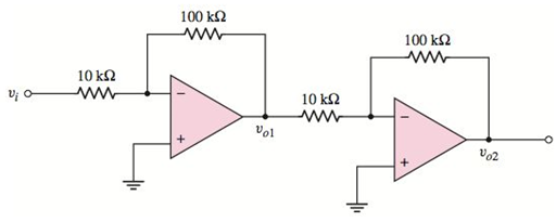
Figure P14.12
Want to see the full answer?
Check out a sample textbook solution
Chapter 14 Solutions
Microelectronics: Circuit Analysis and Design


- Boost Converter Design A boost converter is required to have an output voltage of 8 V and supply a load current of 1 A. The input voltage varies from 2.7 to 4.2 V. A control circuit adjusts the duty ratio to keep the output voltage constant. Select the switching frequency. Determine a value for the inductor such that the variation in inductor current is no more than 40 percent of the average inductor current for all operating conditions. Determine a value of an ideal capacitor such that the output voltage ripple is no more than 2 percent. Determine the maximum capacitor equivalent series resistance for a 2 percent ripple.arrow_forward18 ut of estion 9 In Designing a lag compensator for the shown system, the only thing left is to determine the gain K. Take the closed loop poles ass-0.2 0.9. Determine Ke. R(s) Select one: O a. -7 O b. 1.06 O c. 2.50 O d. 1.94 Oe. 0.88 Ke $+0.5 $+0.05 lag compensator Consider the followin s(s+1) plant C()arrow_forwardQ2. For the circuit shown below, sketch i, & Vo 60 a. Find the conduction angle of the thyristor. b. Find the average output voltage V. R-6.50 f- Go Hz = 27AL = 120x17X10 = 6.4092 075 LO = RrjX= Vo L-17mH 6.5+j6.469=9.128 (44595 075 75V( Es 24 Vm A earrow_forward
- Question 4. Design a C converter by drawing according to the values given below.The C ´uk converter has 24 V input and 36 V output providing 80 W load. In this case, choose Duty ratio, switching frequency, inductor dimensions so that the variation in inductor currents is not more than 5 percent of the average inductor current, output voltage fluctuation is less than 1 percent and voltage fluctuation at C1 is less than 5 percent.arrow_forward2. The circuit given below is using a transformer of 230V/30V. The load resistance is 10KS. Find Vin (rms and peak values), Vdiode and VLOAD (Peak and dc values). Draw the input and output voltage waveforms. (Si diode) Vin: Vin rms= Vin peak = VDIODE Vdiode = 4 Vin VLOAD: VLOAD Peak =. Load VLOAD VLOAD DC= 2031 Supply wwwwwwarrow_forwardWrite the loop equations for a Buck converter in the two modes if the inductance is characterized by a combination of inductance L1 in series with an equivalent resistance r1, filter capacitance is characterized by a capacitor C1 in series with resistance r2. Also assume that the controlled switch has a drop of 0.4V and the freewheeling diode has a voltage drop of 0.65v. Draw the corresponding equivalent circuits in each mode.arrow_forward
- d) Design (Find the values of the R₁, R2, and C₁) an astable multivibrator circuit to have an output waveform as shown below in the figure (tH = 375µs and t₁ = 125µs). (Assume C₁ = C₂ and R₁ # R₂) and determine the frequency of oscillation and the duty cycle. R1: R2 C1 Q Vcc 4 555 5 C2 10nF I 8 1 3L -OVO tH = 375.0us tL = 125.0usarrow_forwardFor distortion readings of D2 = 0.15, D3 Rc = 4 N, calculate the total harmonic distortion fundamental power component and total power. 0.01, and D4 = 0.05, with I1 = 3.3 A andarrow_forwardFor the following circuit in the figure below. Determine Vp-Va (in units of V) for ɛ = = 31.7 V. a Select one: O A. 5.28 O B. -5.28 O C. -6.34 O D. 6.34 O E. -26.42arrow_forward
- Consider a Voltage-Voltage amplifier, input resistance (Rin) and output resistance (Rout) should be Microphone Amplifier Speaker Select one: Oa. none of these O b. Rin ∞ and Rout-00 O C. Rin and Rout-0 O d. Rin 0 and Rout→ ∞arrow_forwardIn the signal flow graph of the given figure, the number of forward paths is * O 1 4 2arrow_forwardCompute for Zin and Zout. Voltage Gain and Current Gain.arrow_forward
 Introductory Circuit Analysis (13th Edition)Electrical EngineeringISBN:9780133923605Author:Robert L. BoylestadPublisher:PEARSON
 Delmar's Standard Textbook Of ElectricityElectrical EngineeringISBN:9781337900348Author:Stephen L. HermanPublisher:Cengage Learning
 Programmable Logic ControllersElectrical EngineeringISBN:9780073373843Author:Frank D. PetruzellaPublisher:McGraw-Hill Education
 Fundamentals of Electric CircuitsElectrical EngineeringISBN:9780078028229Author:Charles K Alexander, Matthew SadikuPublisher:McGraw-Hill Education
 Electric Circuits. (11th Edition)Electrical EngineeringISBN:9780134746968Author:James W. Nilsson, Susan RiedelPublisher:PEARSON
 Engineering ElectromagneticsElectrical EngineeringISBN:9780078028151Author:Hayt, William H. (william Hart), Jr, BUCK, John A.Publisher:Mcgraw-hill Education,