
Videos
The noninverting amplifier in Figure P14.13 has an op−amp with open−loopproperties:
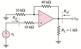
Figure P14.13
Want to see the full answer?
Check out a sample textbook solution
Chapter 14 Solutions
Microelectronics: Circuit Analysis and Design


- Boost Converter Design A boost converter is required to have an output voltage of 8 V and supply a load current of 1 A. The input voltage varies from 2.7 to 4.2 V. A control circuit adjusts the duty ratio to keep the output voltage constant. Select the switching frequency. Determine a value for the inductor such that the variation in inductor current is no more than 40 percent of the average inductor current for all operating conditions. Determine a value of an ideal capacitor such that the output voltage ripple is no more than 2 percent. Determine the maximum capacitor equivalent series resistance for a 2 percent ripple.arrow_forwardFor the following zener clipper draw the output waveform Vz1 = 5V, Vz1 = 7V VK = 0.8v lkn ISV V₁₂ 5V 2, 72. -5V Q2 Determine The Output Waveform And Calculate The current and PIV 1kQ 1kQ 10 V 10 si www www Q. For the circuit shown in Figure below (1),find the maximum and minimum values of zener diod current. Live 5 ΚΩ www I IL 15 80-120 V 10 ΚΩ LIR 101 102 1015 S Ne 1 k0 www Iz 50 V U2 -ot V. Fumal inasharrow_forwardA step down converter is operated with a duty cycle of k = 0.75. The input voltage is Vs = 20V, and the load is: L = 5mH, R = 1502. The minimum inductor current is I₁ = 0.1A. The maximum inductor current is: Select one: a. 1.9 A b. None of these OC. 0.9 A O d. 1.1 A Oe. 2 Aarrow_forward
- A boost converter has an input voltage Vb-5V. The average load current is lo-0SA. The switching frequency is 25 kHz. Suppose that a regulator is added (L=0.15 mH and C-0.22 mF) and that the current is continuous. if the average output voltage is Vo =15V, then the ripple current of the inductor delta) is equal to: Select one: O a. None of these O b.0.89A O C. 1.41A O d. 0.56Aarrow_forwardQ2:-Find the output voltage Vo . Ry B2HF 100 kQ + 100 mV rms,arrow_forwardQuestion 4. Design a C converter by drawing according to the values given below.The C ´uk converter has 24 V input and 36 V output providing 80 W load. In this case, choose Duty ratio, switching frequency, inductor dimensions so that the variation in inductor currents is not more than 5 percent of the average inductor current, output voltage fluctuation is less than 1 percent and voltage fluctuation at C1 is less than 5 percent.arrow_forward
- The buck converter with resistive load has the input voltage of 30[V], the output voltage of 10 [V] (constant), and the switching frequency of 30 [kHz]. If the output average power is 25[W], then determine the size of the inductor such that the minimum inductor current is 25 % of the average inductor current.arrow_forwardThe buck converter with resistive load has the input voltage of 30[V], the output voltage of 10[V] (constant), and the switching frequency of 40 [kHz]. If the output average power is 25[W], then determine the size of the inductor such that the minimum inductor current is 25 % of the average inductor current.arrow_forwardFor the following op-amp circuit, find the complex power and power factor angle associated with the inductor. 2400 5L 200r Vo - 500jsr 1000 lo00j suarrow_forward
- A step down converter has a load resistance R-0.50hms. an input voltage Vs-200V and a battery voltage E-20V. The average load current la=250A and the converter frequency is 400 Hz. The value of the inductance L that would limit the maximum load ripple current to 5% of la, would be equal to: Select one: O a. 9 mH O b. None of these O c. 26 mH O d. 15 mHarrow_forwardDesign a Cuk converter that has an input of 25V and the output of -30V. The load is 60W. Specify the duty ratio, switching frequency, inductor values and capacitor values. The maximum change in inductor currents must be 20 percent of the average currents. The ripple voltage across capacitor C1 must be less than 5 percent, and the output ripple voltage must be less than 1 percent.arrow_forwardExercise 2: Buck Converter Design: Design a buck converter to produce an output voltage of Vo=18 V across a R=10Q load resistor. The output voltage ripple must not exceed 0.5 percent (AVo/Vo). The de supply is Vin=48 V. Design for continuous inductor current. Specify the duty ratio, the switching frequency, the values of the inductor L and capacitor C, the peak voltage rating of each device, and the rms current in the inductor and capacitor. Assume ideal components.arrow_forward
 Introductory Circuit Analysis (13th Edition)Electrical EngineeringISBN:9780133923605Author:Robert L. BoylestadPublisher:PEARSON
 Delmar's Standard Textbook Of ElectricityElectrical EngineeringISBN:9781337900348Author:Stephen L. HermanPublisher:Cengage Learning
 Programmable Logic ControllersElectrical EngineeringISBN:9780073373843Author:Frank D. PetruzellaPublisher:McGraw-Hill Education
 Fundamentals of Electric CircuitsElectrical EngineeringISBN:9780078028229Author:Charles K Alexander, Matthew SadikuPublisher:McGraw-Hill Education
 Electric Circuits. (11th Edition)Electrical EngineeringISBN:9780134746968Author:James W. Nilsson, Susan RiedelPublisher:PEARSON
 Engineering ElectromagneticsElectrical EngineeringISBN:9780078028151Author:Hayt, William H. (william Hart), Jr, BUCK, John A.Publisher:Mcgraw-hill Education,